It’s easier than ever to create a system that plays audio. Greeting cards do it, watches do it, just about any consumer system is capable of playing sound. Yes, the quality is variable, but that abides by the old maxim of, “you get what you pay for”.
So what happens if we have a very low cost piezoelectric element (shortened to piezo for the rest of this article), an NPN transistor, and a microcontroller with PWM capabilities…can we make that do anything fun from Zephyr? It turns out, yes, we can. Let’s take a look.
Simplicity
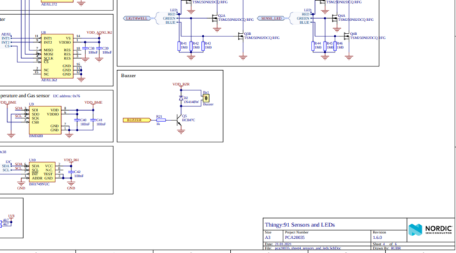
The hardware components on the schematic are pretty bare bones. The output pin from the microcontroller drives an NPN transistor, which then draws current down through a piezo. If we vary the on-off nature through the piezo, we’ll get a tone that matches the frequency of the AC waveform we are using. Using a frequency of 440 Hz should result in an A4 tone. In fact, it does!
The on-off nature of a PWM signal creates a square wave. This creates harmonics that produce a recognizable, if not harsh, tone. Songs with tonality like this are sometimes referred to as “chiptune“, because of its association with early video games and their limited capabilities to generate more complex waveforms. Personally, I have a lot of positive associations with this style of sound and music, since I grew up with early games that employed this type of music; it has also developed as a musical subgenre. But for today’s article, all that’s necessary to know is that we will be generating simple square wave tones, which produces a particular sound (examples in a video below).
Another important element is that there is only one generator of sound being used. This means the sound will be monophonic (“one voice”), as opposed to more complex polyphonic sounds, even within the chiptune genre. So like we said, this will be a simplistic output.
Zephyr challenges
Now that we know the hardware, how do we actually get the PWM generator inside a microcontroller to output the waveform we want?
For this exercise, we will be using the Nordic Semiconductor nRF9160, based on a dual core Cortex-M33 part with some standard PWM peripherals built in. However, because we are using Zephyr, the actual register map of the Nordic-specific PWM are not important. Instead, we will be interacting with the standard Zephyr PWM peripheral and APIs. This level of abstraction is implemented in the Zephyr ecosystem by Nordic Semiconductor and the community, and is also implemented by other chip vendors who participate. The net result is that code interacting with the Zephyr PWM element should work with any device that is supported in the Zephyr ecosystem.
We had trouble finding code that was already written for driving the piezo, so we decided to dig into the PWM peripherals. This is where things got confusing.
PWMs only for LEDs?
The first confusing fact is that all of the references to PWM in existing code seemed to apply only to LEDs. PWM is a great use case for LEDs and we implemented this in a thread on our Thingy91 code and pre-compiled binary to help show device status. But what about an alternative PWM device that’s not an LED?
The issue exists in the “compatible” keyword in the devicetree overlay. We only found pwm-leds as a compatible type. We spent a bunch of time chasing other types and seeing if we should use it, but at the end of the day we shrugged and decided our buzzer wouldn’t be bothered being called an ‘led’ in this way. Below is what our thingy91 overlay file looks like.
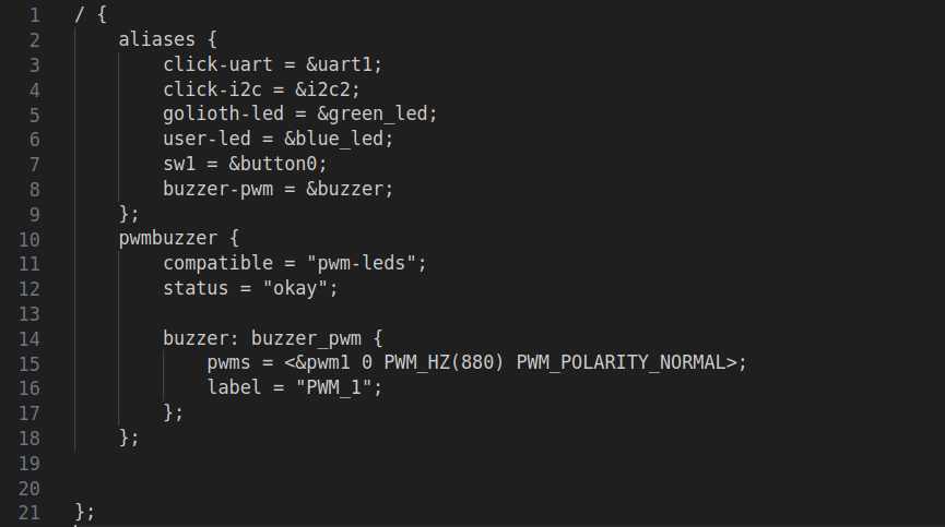
The pwms field is all we’re really going to be messing with in the program, so we set it to something that made sense for a getting started value and moved on.
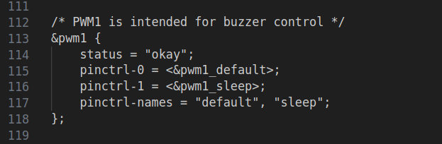
You’ll also note that it refers to &pwm1 in that line. It is calling out a PWM element in the hardware that is also called out in the thingy91_nrf9160_common.dts file as a placeholder to be used with the buzzer. This could be used for other features as well, but the Thingy91 has a limited set of peripherals and not many ways to break out signals, so it makes sense that it was “reserved” for the buzzer, despite not being plumbed in otherwise.
We call out the devicetree entry in the overlay file using the following line in app_work.c (view the entire thingy91_golioth project here)
const struct pwm_dt_spec sBuzzer = PWM_DT_SPEC_GET(DT_ALIAS(buzzer_pwm));
This gives us a struct to work with. When we want to turn the buzzer on, the call looks like
pwm_set_dt(&sBuzzer, PWM_HZ(1000), PWM_HZ(1000) / 2);
We’re passing in the handle sBuzzer and then telling it to play a tone at 1 kHz with a cycle time of 500 Hz–a 50% duty cycle. Since we’re creating a square wave, we can keep the duty cycle at 50% and then vary the frequency to change tones. For things like LED fading, we’d actually change the duty cycle but not the frequency (see other parts of the thingy91_golioth repo for example of LED fades).
Framework
So now we can play a 1 kHz tone, which works great for a buzzer. But what about when we want to easily add a bunch of different notes? To get recognizable notes into the code, we set up a struct that ties together a frequency and a duration:
struct note_duration
{
    int note; // hz
    int duration; // msec
};
We also put a bunch of lookup values into the app_work.h header file:
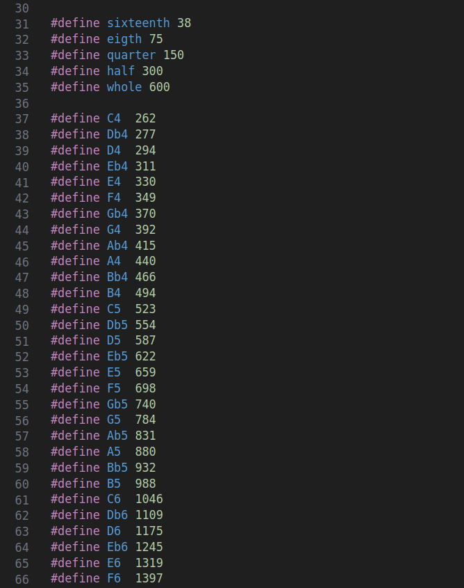 The note durations were hard-coded in here, but could also be set to be a multiplier of a song tempo, if you wanted a faster or slower song; each note is just a fraction of the overall tempo. The notes are simple frequency lookups. If you don’t have a music background, check out how each increasing octave of a particular note is double the frequency of the note an octave below (ie. A5 is 880 while A4 is 440). Music is math!
Songs
Now that we have a framework for creating songs, it’s all about translating sheet music into an array of notes/durations. This is what our version of “funkytown” looks like:
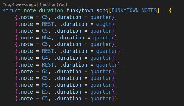 The
The REST note sets the frequency to 1 Hz. Since the small piezo is not capable of playing low frequency notes (think about how large most speaker woofers need to be for playing bass loudly), we treat anything less than 10 Hz as a “skip” or “rest”.
All of this is done in an RTOS thread dedicated to playing the song. We pass in which song we want to play, cycle through a for loop playing all the notes in the array and then the thread goes back to sleep. The nice thing is that the buzzer is set as an extremely low priority, so if anything else important is happening in the system, the RTOS scheduler will switch to that task. Even when it’s interrupted to go handle something like an incoming message on the cellular modem, it’s not a noticeable change in how the song sounds. See the app_work.c code to see how this thread operates.
See it in action
This standalone video shows the songs being triggered using the Golioth Remote Procedure Call (RPC) service.
Since we’re running the piezo music in a separate thread, we can receive the RPC, process which song we want to play, and then wake up the thread with the requested song that was passed over the internet.
What will you build?
It takes a lot of tech to play a song over a cellular network, but it helps showcase all the things you can do with Zephyr, Golioth, and Nordic Semiconductor hardware. Of course you can always modify our thingy91_golioth repo and play any other song you’d like…or you can expand on these capabilities and build a wide range of other IoT applications. Our Reference Designs give a good idea of real-world applications you can achieve with the Golioth platform. We’d love to hear about what you’re building on our Forum!

No comments yet! Start the discussion at forum.golioth.io