
The Inside Story of the Golioth Bluetooth® Mesh Demo
My previous article described a demo that used the Golioth console to send RPCs (Remote Procedure Calls) and device settings to a Bluetooth Mesh. The purpose was to show how easy it is to control a Bluetooth Mesh from an internet connected device. This article is to give some details as to how I created the demo.
But first, let me give you a quick tutorial on the Bluetooth Mesh LC server (the following diagram represents the information from the Bluetooth® SIG specification MshMDL_v1.1):
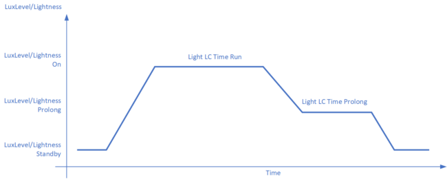
The Y-axis is the brightness of a luminaire (“the device that is lighting up”). LuxLevel/Lightness is defined for three levels: On, Prolong, and Standby. The general rule is that On is the brightest setting, Prolong is dimmer than On, and Standby is the dimmest (or completely off). The X-axis is the time axis during which the luminaire maintains each of those lightness levels.
Each bbc:microbit in the demo implements an LC Server which while following the above diagram:
- Transitions the LEDs to the “On” lightness level (LuxLevel/Lightness On)
- Stays at that lightness level for the “Run” time (Light LC Time Run)
- Dims the LEDs to the “Prolong” lightness level (LuxLevel/Lightness Prolong)
- Stays at that lightness level for the “Prolong” time (Light LC Time Prolong)
- Dims the LEDs to the “Standby” level (LuxLevel/Lightness Standby)
The Device Settings
The demo needed a way of setting these five parameters (the three lightness levels and two times). The Device Settings page of the Golioth console was ideal for this. I mapped the settings as follows:
- Device setting name
- TIME_RUN
- TIME_PROLONG
- LVL_RUN
- LVL_PROLONG
- LVL_STANDBY
- LC server value
- Light LC Time Run
- Light LC Time Prolong
- LuxLevel/Lightness On
- LuxLevel/Lightness Prolong
- LuxLevel/Lightness Standby
And of course, the Mesh firmware specifies default values for each of these. But when doing demos (or development), there are many times you want to change these values. If you don’t have a handy LC client around, you often resort to changing the defaults in the firmware and pushing over the air updates. And if you have 8 (or more) LC servers to update in a mesh, that gets painful quickly.
In the demo, you can set TIME_RUN to 5 seconds, so when the LEDs first turn on, they stay “On” for 5 seconds. If that time is too short for you, set it to 20 seconds, and the next time the LEDs turn “On”, they stay there for 20 seconds. Similarly with TIME_PROLONG – you easily define how long the lights stay at “Prolong.”
And then comes the individual light levels – do you want the Run level to be 100%, Prolong at 50%, and Standby at 0% (off)? Then all you need to do is change a setting. Voilà, it’s done. This is much easier than modifying every LC server firmware on each device, every time you want to view a new set of levels and times.
The astute reader will notice that there are other values in the diagram above (and there are several other values in the LC Server model as well), but only a subset is implemented for simplicity’s sake.
The Remote Procedure Calls
Now what about those RPCs? Several were written specifically for this demo, turning the LEDs on and off in different ways. Some turn off the control of the LC server, and some turn it back on. The following functions were implemented:
set_light- This is often the first RPC sent – it demonstrates the basic LC model functionality. A
set_light onRPC tells the microbits to follow the LC server diagram (shown above). Each microbit ramps its LEDs to the “On” lightness level, then starts dimming, eventually ramping back to “Standby”. Aset_light offRPC tells the microbits to immediately set the LEDs to “Standby”, bypassing the ramping and the “Prolong” level. Note that pushing the button on the Thingy91 sends the same command as theset_lightRPC.
- This is often the first RPC sent – it demonstrates the basic LC model functionality. A
lightness- This RPC overrides the lightness level, turning off the LC server. The lightness will stay at the specified percentage level until another command is received.
lc_mode- This RPC turns the LC server on or off. This sends the LC model command to turn on/off the server. Anytime the LC server is turned off (e.g., with a lightness command), this is the only command that can turn it back on.
gen_on_off- This RPC is specific to the structure of an LC server. Every LC server node has at least two elements – one with a Lightness Server, and one with an LC server. The
gen_on_offRPC sends a generic on/off command to the specified element. The first parameter is the on/off command (1 == on, 0 == off), and the second parameter specifies the element (0 == LC server, 1 == Lightness server).
- This RPC is specific to the structure of an LC server. Every LC server node has at least two elements – one with a Lightness Server, and one with an LC server. The
How Does the Code Know about Changes to the Device Settings?
Golioth provides a registration function for device settings. The firmware passes a callback function to the register function. Anytime a device setting changes, the callback function is invoked, and it receives:
- The string name of the setting (e.g., “TIME_RUN”)
- A structure containing the value.
The firmware then does a simple name string comparison, and then we send that value on to the Mesh (more about that later).
int err = golioth_settings_register_callback(settings_client, on_setting);
if (err) {
    LOG_ERR("Failed to register settings callback: %d", err);
}
And the definition of the on_setting() callback:
enum golioth_settings_status on_setting(const char *key, const struct golioth_settings_value *value)
{
…
    if (strcmp(key, "TIME_RUN") == 0) {
        /* time in seconds - numeric */
        if (value->type != GOLIOTH_SETTINGS_VALUE_TYPE_INT64) {
            LOG_DBG("Received TIME_RUN is not an integer type.");
            return GOLIOTH_SETTINGS_VALUE_FORMAT_NOT_VALID;
        }
        /* Only update if value has changed */
        if (_time_run_sec == (int32_t)value->i64) {
            LOG_DBG("Received TIME_RUN already matching local value.");
        } else {
            _time_run_sec = (int32_t)value->i64;
            _time_run_changed = true;
            // tell system thread to send the property data across the UART to
            // the BLE chip
            wake_system_thread();
        }
        return GOLIOTH_SETTINGS_SUCCESS;
    }
…
}
How Does the Code Know About RPCs?
It’s a slightly different mechanism, but straightforward: Golioth provides an RPC registration function. For every RPC you create, provide it to the registration function along with a string (linking your RPC function to the string name in the console). When the string name is invoked in the console, the local RPC function is called, passing any provided parameters. In the demo, we send that information to the Mesh (more on that later). Code snippet:
err = golioth_rpc_register(rpc_client, "lightness", on_lightness, NULL);
rpc_log_if_register_failure(err);
And earlier in the file we defined RPC function on_lightness() as:
static enum golioth_rpc_status on_lightness(zcbor_state_t *request_params_array,
                                            zcbor_state_t *response_detail_map,
                                            void *callback_arg)
{
    bool ok;
    double valuef1;
    uint8_t value1;

    ok = zcbor_float_decode(request_params_array, &valuef1);
    if (!ok)
    {
        LOG_ERR("Failed to decode RPC int1 argument");
        return GOLIOTH_RPC_INVALID_ARGUMENT;
    }

    value1 = (uint8_t) valuef1;
    LOG_DBG("Received argument '%d' from 'lightness' RPC", value1);
    send_lightness(value1);

    return GOLIOTH_RPC_OK;
}
Passing commands between nRF9160 and nRF52840
Up to now, everything has been communication between the nRF9160 and Golioth (via LTE-M or NB-IoT). So now the nRF9160 is going to send this information to the nRF52840 (the BLE chip configured as an LC client). The UART is a convenient communication path provided by the Thingy91. When any device setting changes or an RPC is called, the nRF9160 maps that to a series of bytes to send to the BLE chip.
For example, when the nRF9160 calls send_lightness(value1), it executes:
bytebuf[0] = '3'; // lightness cmd – character
bytebuf[1] = v1;  // integer val, not character - percentage
err = uart_tx(Uart, bytebuf, sizeof(bytebuf), SYS_FOREVER_US);
which sends those two bytes to the BLE chip. Upon receiving the UART data, the BLE chip parses the lightness command, grabs the lightness value, and then sends a Bluetooth Mesh lighting command to tell the micro:bits to set the lightness value.
How does the BLE chip (the nRF52840) send Mesh commands?
The Bluetooth Mesh has a different communication method from the traditional BLE central/peripheral characteristic write/read method. The Mesh doesn’t really have the idea of a connection, nor of a central or peripheral. Every device on the Mesh is called a node, and Mesh nodes send messages that every node on the Mesh can hear (more details in a future blog).
For the demo, the nRF52840 has been programmed as a full Bluetooth Mesh node – specifically as a client (it sends commands to servers). Each LC server (micro:bit) listens for commands from the nRF52840 clients. Yes, that is plural – clients…The nRF52840 node has
- One LC client
- Two Generic On/Off clients
- One Lightness client.
When the node wants to send the LC mode command, it uses the LC client function:
int bt_mesh_light_ctrl_cli_mode_set(…,…,bool enabled,…);
where the “enabled” parameter will set the LC Mode on or off.
When it wants to send a Lightness command, it uses the Lightness client function:
int bt_mesh_lightness_cli_light_set(…,…,… *set,…);
where the “set” parameter points to a structure containing the lightness level.
In general, when a node needs to send a Mesh command, it calls the appropriate client model function to send it. So, when an LC model command needs to be sent, we call an LC client model function. When a Generic On/Off model command needs to be sent, we call a Generic On/Off client model function (and similarly with Lightness commands, or any of the other commands that have been defined in the Bluetooth Mesh Model Specification).
And then the micro:bits?
The final piece of the puzzle is the micro:bits – they are programmed as mesh nodes, implementing the LC server. Each one “hears” the commands from the client node, and independently acts upon those commands. Note that each server node can return status(es) as a result of these commands, and the client node can act upon these statuses (this was not implemented in the demo, for simplicity).
The full signal chain, described
So now you have an overview of the process – specifically how:
- The nRF9160 receives the device settings and RPCs from the Golioth console,
- The nRF9160 sends that info over the UART to the nRF52840,
- The nRF52840 sends that info, translated into Bluetooth Mesh commands, to the rest of the nodes in the Mesh (the micro:bits).
Bluetooth Mesh and the LC server nodes are simple in concept, but often difficult in execution. With the Thingy91 running the Golioth Firmware SDK, it has gotten a lot easier to control and extend Bluetooth Mesh demos to show to clients.
 OTA on the nRF9160 with Golioth")
 Public domain image source: https://www.pexels.com/photo/vintage-brown-crt-tv-on-parquet-wood-flooring-333984/


Start the discussion at forum.golioth.io