Most of the time we’re writing about how to build out the firmware that will go onto your IoT Devices. Our device Software Development Kits (SDKs) are a key offering that Golioth provides to hardware and firmware engineers; we want it to be easier for you to build the code that will go onto the device out in the field. Once the code is ready to go, you need to think about how you are going to enclose the thing you just made, whether it’s a product or a prototype.
We have been building prototypes in the form of Golioth Reference Designs. These are end-to-end demos that include hardware, firmware, software, and visualization, and we’ve been building a bunch of them. That has meant we are developing a “high mix, low volume” set of products (really prototypes) and have needed to figure out how to utilize enclosures for the different things we’re trying to do.
What’s in the box
Most of our current Reference Designs contain a few key things:
- A development board, such as the Sparkfun Thing Plus nRF9160 (our current most-used board)
- Sensor boards or interfaces to external items
- A battery
- A centralized board that makes it easy to mount each of the above items
Off-the-shelf hardware like this is less a “product” than it is a first round prototype or even Proof-of-Concept. It can be used to test a business idea or to build requirements for a future high volume product.
Requirements influence design
We have tried a few different ways of enclosing our projects so far. As you’ll read below, each time we built something, we took the lessons we learned and modified our next iteration.
Color demos (Aludel)
Our first round of assumptions was that we needed to make everything waterproof and have maximum flexibility. As such, we decided on the Bud model PN-1324-CMB. It’s a normally gray opaque base with a clear polycarbonate lid where we could have a display element on a top PCB. The main function was that we could implement lots of cabling internally but still have access to Click boards (based on the Mikroelectronica MikroBus standard). The cabling would all go through cable glands to keep out moisture. I also liked that the box had flanges so we could screw this unit to a wall or a display stand.
This method worked out OK but had the downside of requiring each sensor to be either outside the box and cabled in or we needed to “break” the waterproof nature to monitor things like air humidity. Most things we were planning to do involved direct monitoring of the environment. This, in combination with the large overall size of the demos, meant that we thought we could improve on future revisions.
You can see these cases in action (including cover plates that hid the base PCB) in the green and blue demos that we took to Embedded World in 2022.
Trashcan Reference Design – First iteration
Since we were monitoring using a time-of-flight sensor on the Trashcan Reference Design, I knew we would need the sensor to be external to the case. Or at least it would need to be pointing outside the envelope of the case, as shown below. I used a Sparkfun breakout board for the VL53L0X sensor from ST Micro and drilled out a hole to allow the signal to point down into a trashcan and reflect off the top of the trash piled up inside that can. Then I hot glued it in place.
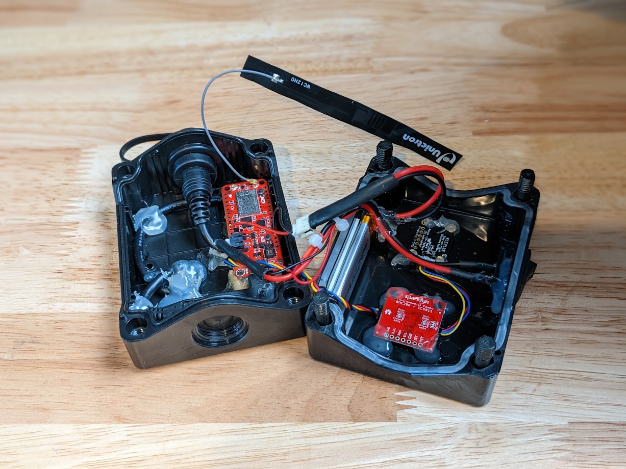
This is unrealistic in a deployment as a trashcan is a harsh environment, especially deployed somewhere like a national park. The moisture and heat inside a trashcan would require the device be more watertight. After building this iteration and realizing we were not designing something deployable, my mindset around how we needed to make our cases began to change. It would be imperative on anyone who utilizes our reference designs to make revisions, optimizing it for manufacture and hardening it for their specific environmental needs. What is the impact if our Reference Designs are no longer planned to be field ready or watertight?
Trashcan Reference Design – Second Iteration
In the second iteration of the Trashcan Reference Design, I started to optimize for some different elements, most noticeably the repeatability of the design. There is nothing special about the PCB shown below, only that it can be manufactured more easily than the hotglue-laden prototype in the first iteration. Again, we see that the design is not water tight. I did focus on maintaining a smaller form factor than the Aludel, with a low cost case.
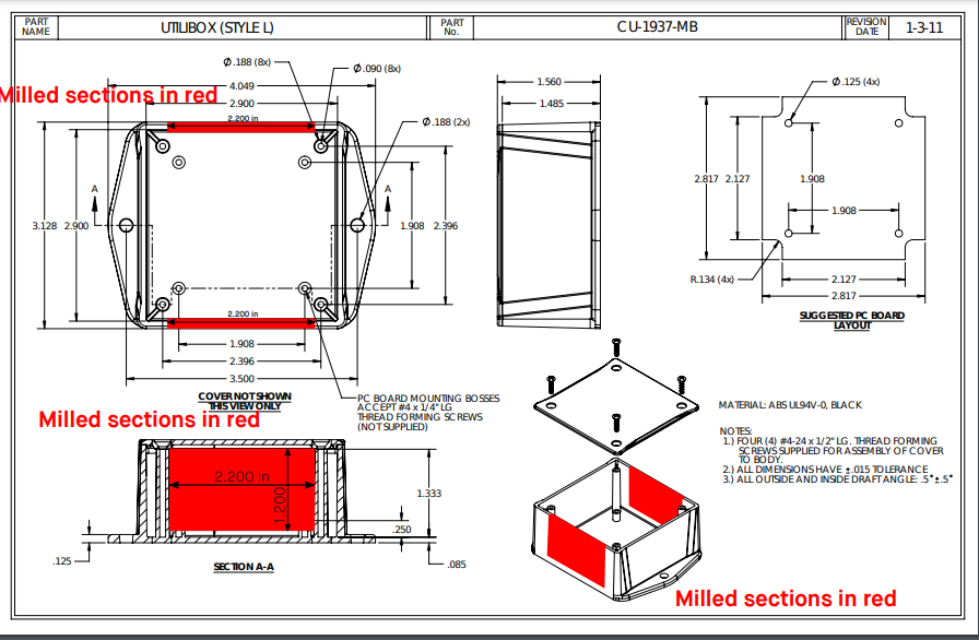
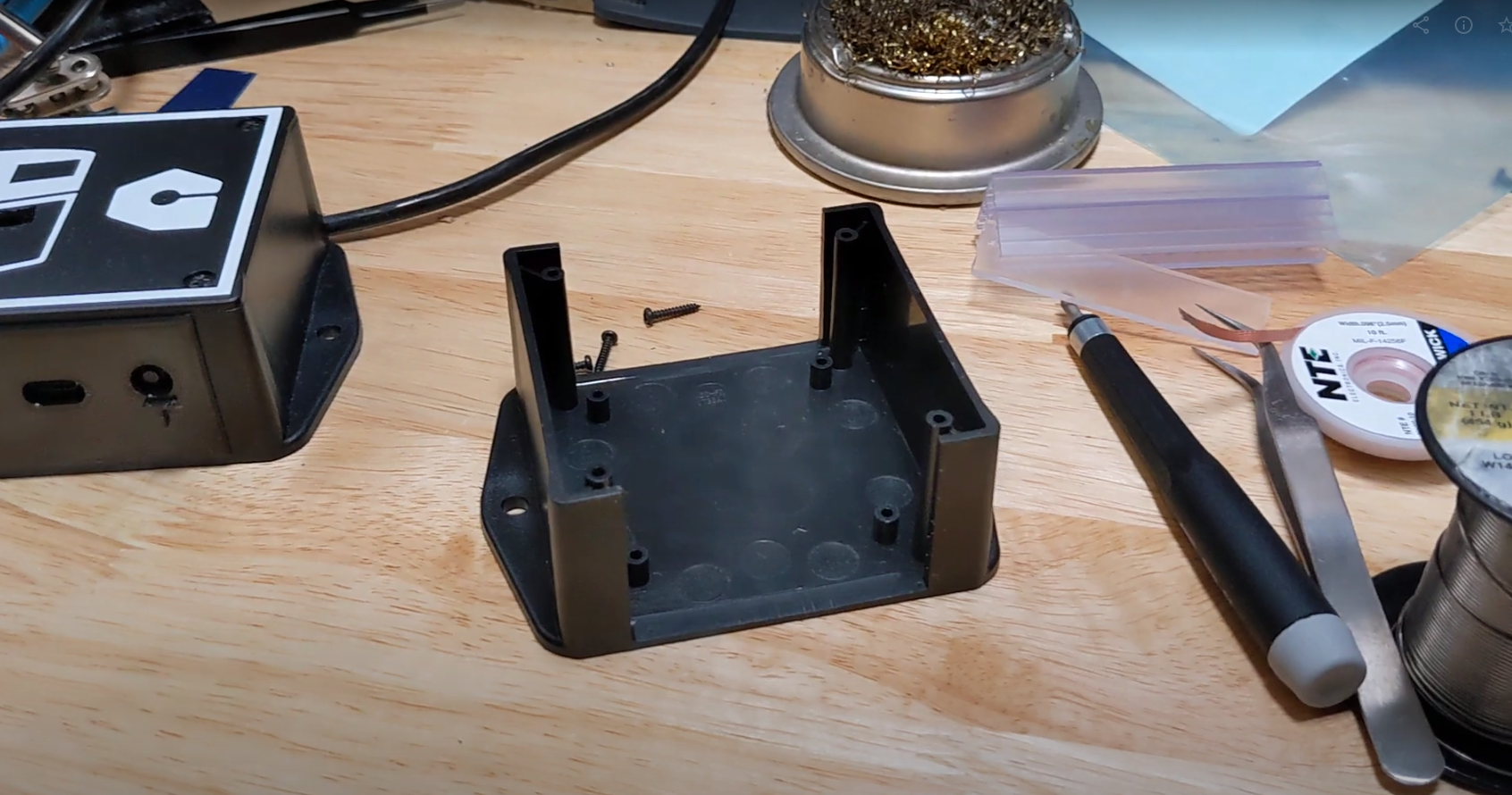
This one is the Bud CU-1937-MB, part of their “Utilibox” line. Not designed to show much of anything, it’s meant to really be screwed to the wall and forgotten (as many IoT things are). I once again chose a design that had flanges as part of the case for easy mounting on a wall; in this case, it’d be mounted on the underside of a trashcan lid.
The difficulty was in a non-standard cutout. Also the fact that I was using a Dremel hand tool instead of something more precise like a milling machine. This goes back to the “high mix” element, it was tough to justify buying a milling machine and then programming it or getting better at manual machining. I took my best shot with a Dremel (spending quite a bit of time in the process) and then 3D printed a thin case over top of the quite ragged holes that I cut.
Most people wouldn’t/won’t see this element of the design, but it’s still important not to have holes cut out that are all jagged and rough.
Aludel Mini
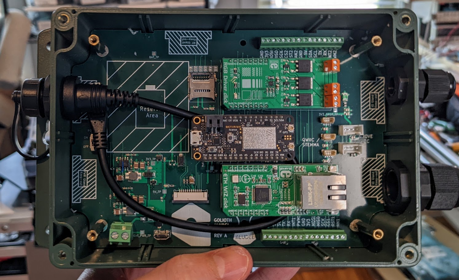
In our most current iteration on display at Embedded World coming up in 2 weeks, I decided to take a different tack, based on some brainstorming with my coworker Mike. We had already re-designed the landing board to once again utilize Click boards from Mikroelectronica, and to fit in the same case (CU-1937-MB); this was called the “Aludel mini”, playing off the name of the original Aludel case design.
It was unclear at first if we could fit the size of the headers (in width and height) into that case, but it turns out we can. We really liked that there is a wide variety of sensors available in that form factor and we can also buy things like the Arduino to Click converter boards to make the same sensors available on platforms like the nRF9160-DK.
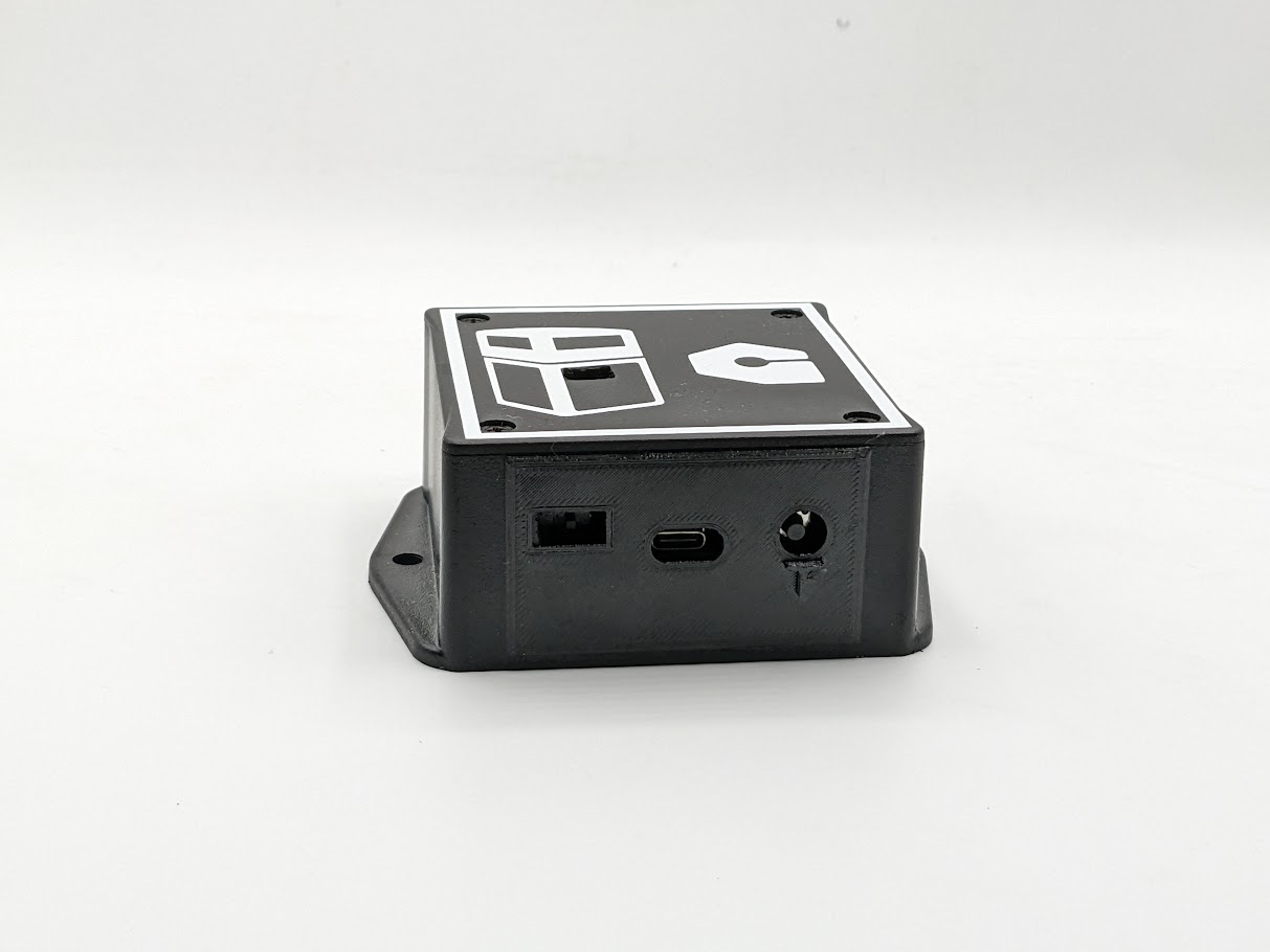
So now that we know we are using that same case and that we are somewhat OK with a 3D printed element on that case, I decided to take a leap and have Bud modify the boxes to plan for this flexibility. Instead of having them mill out just the button and USB C port cutouts, I decided to have them basically wipe out two of the walls of the case. That might be a bit extreme, but it allows for ultimate flexibility.
This was a custom order (with an upcharge for doing so, understandably), but it was a pretty seamless process to go back and forth with the manufacturer rep (Pinnacle Marketing, based on my location in the US Southeast) and the manufacturer (Bud Industries) and get these made. They did warn that the structural integrity of the case would be impacted, but I moved forward knowing we would be able to reinforce with the inserts we design.
Now the trick was to design something that could fit this shape. They have a high draft angle, ostensibly to make it an easier ejection from injection molding equipment, but that makes for some odd trapezoidal walls. I brought the supplied 3D model into FreeCAD and set to work printing and iterating on the design. Here’s the shape I ended up with:
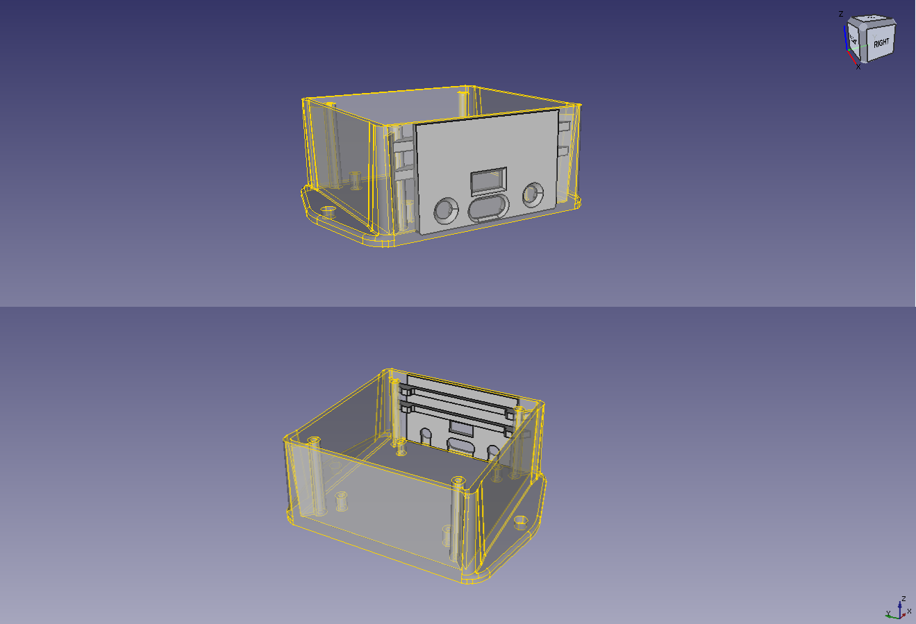
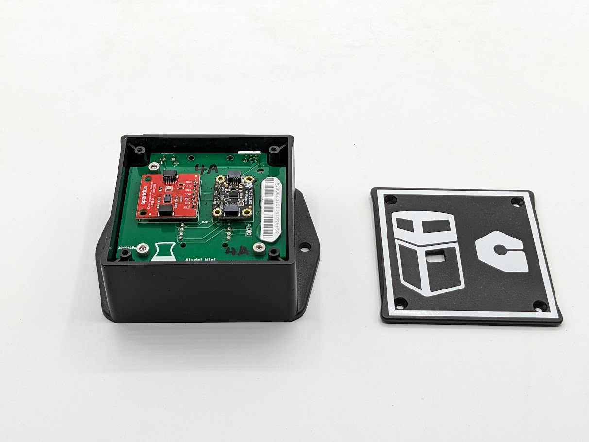
I utilized the mounting posts for the top case as a reinforcing element. For most of the designs I put this into, I’ll glue the plate in place, but it is also designed to slide in and out for prototypes.
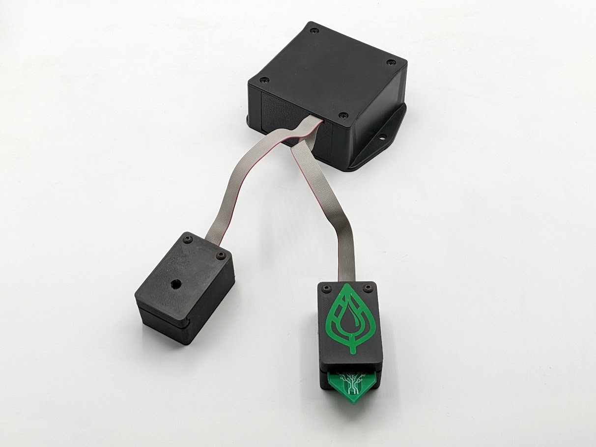
On the other side of the board, we expect there to be much more variation. Often this is where wires or extension cables are interfacing with the case. I took the base plate and was able to draw simple shapes onto the face plate to create a variation for each reference design that we make. This will depend on the type of Click board we have plugged into the Aludel Mini. For the Soil Moisture Reference Design, you can see that I made a cutout that allows the Click Shuttle Expander to go out to individual boards:
The obvious question
With all of these modifications, the obvious question is: Why not 3D print the entire thing?
A fair question, and definitely something that I might consider in a future iteration. I would still want to maintain many of the same features that we have put into the existing designs (relatively small envelope, mounting flanges, plain exterior). The cost would be roughly the same if sent to China for 3D printing (depending on material used), when compared to a low volume run of modified cases + printed inserts. I also like the implied constraints of choosing an enclosure and then needing to work around those constraints, although the exercise changes when designing a product. It prevents adding “just one more thing”, when in our case we’re primarily trying to showcase the platform and not the hardware itself.
High mix is not the norm
Most product companies work differently. If you are spending enough money to hire engineers to design a product, you are likely making a higher volume of devices to support the salaries of engineers. In that case, your constraints change quite a bit. When moving to a higher volume manufacturing run, it makes sense to take everything you learn from a Golioth Reference Design and spin it into a higher volume product (custom PCBs, integrated sensors, more complex battery management, bespoke watertight enclosures, etc). If you want to take Reference Designs for a spin and use them as the basis of your next product, we’d love to talk. If you’re more interested in chatting about how to optimize cases for a variety of different designs, post about it on our forum!
No comments yet! Start the discussion at forum.golioth.io