In the last post in our series on the Constrained Application Protocol (CoAP), we explored some of the trade-offs between reliable and unreliable data transmission. We also covered why the CoAP’s flexibility makes it a good choice for Golioth and constrained applications in general. In this post, we’ll dig deeper into the lifecycle of a CoAP message. What has to happen for data to get from a device in the field to a service in the cloud? What about back again? As we traverse that path, we will describe each protocol along the way.
Setting Up
Throughout this post, we will use the Linux port of the Golioth Firmware SDK at v0.7.0 to communicate from a local machine to Golioth. Specifically, we’ll be examining traffic from the Golioth Basics sample application, which currently uses pre-shared keys (PSKs) for authentication. This is a simpler model than those used by most constrained devices when communicating to Golioth, but it is useful for detailing the general sequence of operations.
We are also going to cheat a bit in this post by describing only communication from OSI Layer 3 and up, but I promise I’ll make it up to you in a painfully lengthy post about framing and modulation in the future.
We’ll use Wireshark to observe network traffic. If you want to view the decrypted CoAP payloads captured by Wireshark, you’ll need to go to Edit > Preferences > Protocols > DTLS then add your PSK in hex form. This can be obtained with the following command.
$ echo -n "YOUR_PSK_HERE" | xxd -ps -c 32
If you would like to follow along with the exact packet capture that we use in this post, you can find it, along with instructions for how to import into Wireshark, in the hasheddan/coap-pcap repository.
Life Before CoAP
When interacting with Golioth via the firmware SDK, it appears as though communication begins when the first CoAP message is sent. However, a number of steps are required before two endpoints can communicate over a Layer 7 protocol like CoAP.
Address Resolution
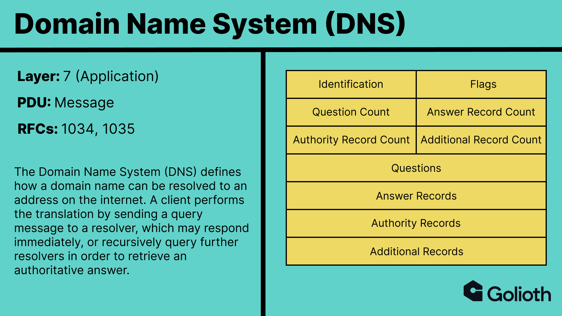
Because humans need to interact with and write programs that interact with the internet, we need to be able to specify the host with a “friendly” name. These names are referred to as domain names on the internet. For example, to read this blog post, you navigated to goliothblogdev.wpenginepowered.com. However, your computer doesn’t know how to find this blog using that name, so it instead needs to translate the name to an address. The common analogy here would be telling my maps app that I want to go to my local coffee shop, Press, to get a crepe. The app needs to translate Press to an address of a physical location before using GPS to navigate there.
The Global Positioning System (GPS) is a protocol that we are not going to talk about at length in this post, but it is equally fascinating as those that we are.
This translation step not only allows us to use more friendly names when we talk about a destination, it also allows that destination to change its physical location without all other services needing to change how they find it. On the internet, the protocol that enables this translation is the Domain Name System (DNS).
The Golioth firmware SDK defines the URI of the Golioth server with the CONFIG_GOLIOTH_COAP_HOST_URI config value.
#ifndef CONFIG_GOLIOTH_COAP_HOST_URI
#define CONFIG_GOLIOTH_COAP_HOST_URI "coaps://coap.golioth.io"
#endif
This value is parsed into the coap.golioth.io domain name when the client is created and a session is established.
// Split URI for host
coap_uri_t host_uri = {};
int uri_status = coap_split_uri(
        (const uint8_t*)CONFIG_GOLIOTH_COAP_HOST_URI,
        strlen(CONFIG_GOLIOTH_COAP_HOST_URI),
        &host_uri);
if (uri_status < 0) {
    GLTH_LOGE(TAG, "CoAP host URI invalid: %s", CONFIG_GOLIOTH_COAP_HOST_URI);
    return GOLIOTH_ERR_INVALID_FORMAT;
}

// Get destination address of host
coap_address_t dst_addr = {};
GOLIOTH_STATUS_RETURN_IF_ERROR(get_coap_dst_address(&host_uri, &dst_addr));
The lookup is ultimately performed by a call to getaddrinfo.
struct addrinfo hints = {
        .ai_socktype = SOCK_DGRAM,
        .ai_family = AF_UNSPEC,
};
struct addrinfo* ainfo = NULL;
const char* hostname = (const char*)host_uri->host.s;
int error = getaddrinfo(hostname, NULL, &hints, &ainfo);
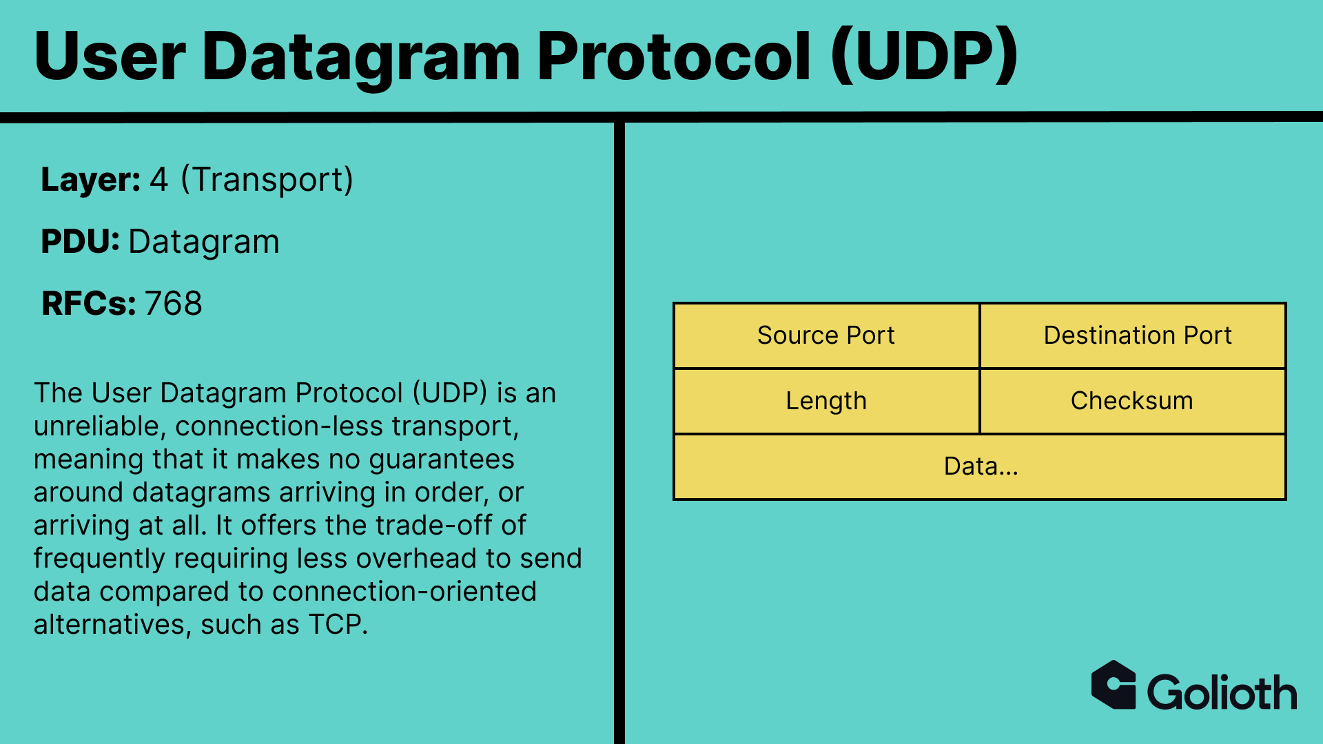
While DNS, like many Layer 7 protocols, can be used over a variety of underlying transports, it typically uses UDP.
Any DNS messages we send are encapsulated in the payload of a UDP datagram, which is supplemented with
- Source port
- Destination port
- Length
- Checksum
This information is in the header. The ports inform what service at the destination the data should be routed to. DNS uses port 53, so the destination port in our UDP datagram header should be 53. However, we still haven’t specified which resolver we want to send the query to. In this case, we need to know the physical address because we can’t ask the resolver to resolve addresses for us if we can’t resolve its address in the first place.
On the internet, these addresses are known as Internet Protocol (IP) addresses.
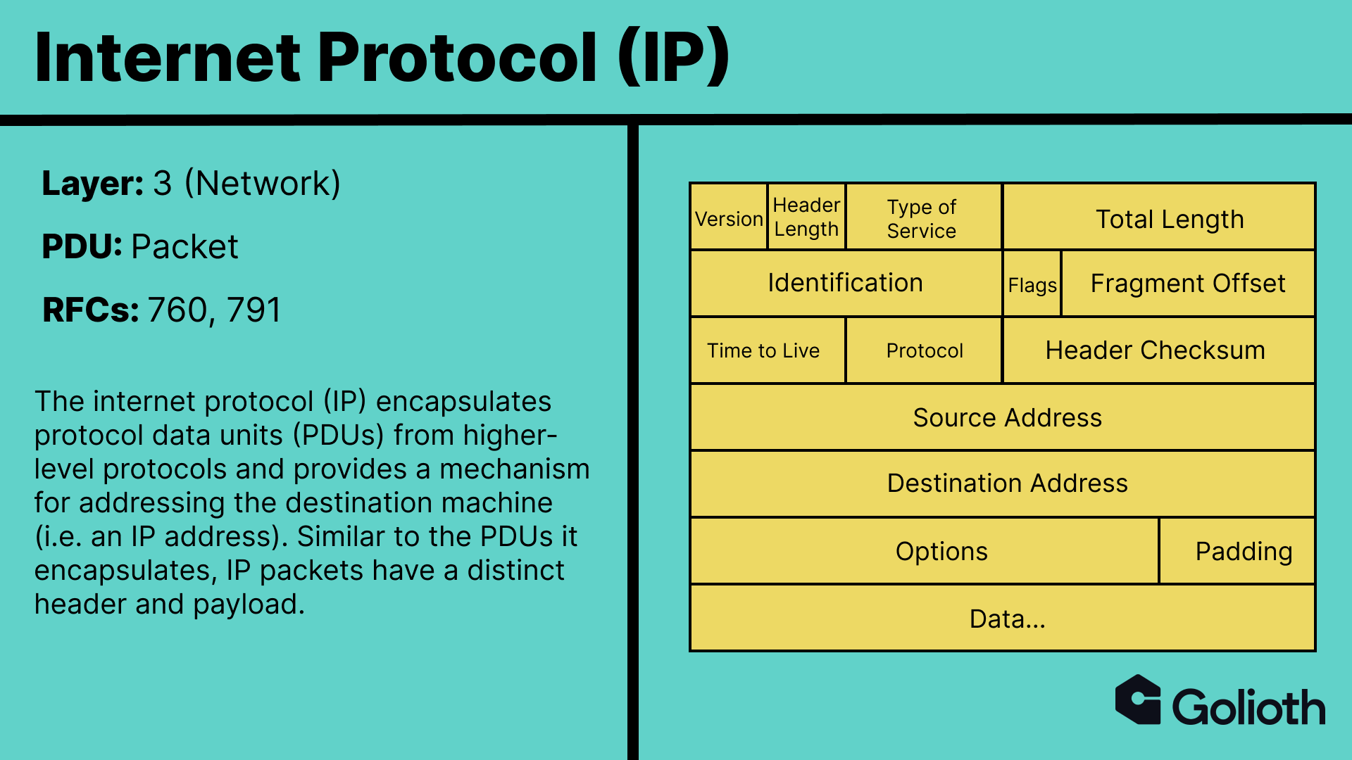 The resolver chain is highly dependent on the configuration of the system in use. My local Ubuntu system uses a local resolver,
 systemd-resolve, which is listening on port 53.
$ sudo netstat -ulpn | grep "127.0.0.53:53"
udp        0      0 127.0.0.53:53           0.0.0.0:*                           827/systemd-resolve
The first packets we see in Wireshark after running the Golioth basics example correspond to attempted DNS resolution of coap.golioth.io.
The first two requests are to systemd-resolve, one for the IPv4 record (A) and one for the IPv6 record (AAAA). systemd-resolve subsequently makes the same requests from my local machine (192.168.1.26) to the router on my home network (192.168.1.1). The response from the router is then returned to systemd-resolve, which returns the answer to our program. Breaking apart the first query message, we can see our three layers of encapsulation.
 The answer in the second to last packet for the
 coap.golioth.io IPv4 address contains the expected IP address, as confirmed by a simple dig query.
$ dig +noall +answer coap.golioth.io
coap.golioth.io.	246	IN	A	34.135.90.112
Establishing a Secure Channel
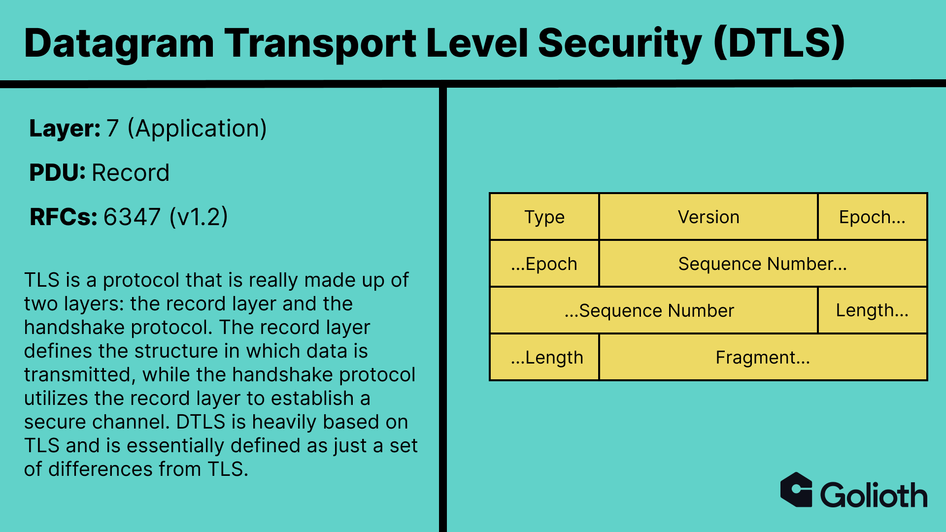
At Golioth, we believe that all data transmission should be secure. In fact, we go so far as to not allow for sending data to the Golioth platform unless it is over a secure channel. Your browser hopefully shows a lock symbol to the left of your address bar right now. That indicates that your request for this web page, and the content of the page that was sent back by the server, happened over a secure channel. This secure channel was established using Transport Layer Security (TLS). However, TLS was designed to run on TCP, and thus requires the presence of a reliable transport, which UDP does not provide. In order to enable the same security over UDP, Datagram Transport Layer Security (DTLS) was developed.
Some of the differences that DTLS introduces to TLS include:
- The inclusion of an explicit
Sequence Number– DTLS must provide a facility for reordering records as UDP does not do so automatically. - The addition of retransmission timers – DTLS must be able to retransmit data in the event that it never arrives at its destination.
- Constraints around fragmentation – While multiple DTLS records may be placed in a single datagram, a single record may not be fragmented across multiple datagrams.
- Removal of stream-based ciphers – TLS 1.2 used RC4 as its stream-based cipher, which does not allow for random access and thus cannot be utilized over an unreliable transport.
- Guardrails against denial-of-service attacks – Datagram protocols are highly susceptible to denial of service attacks due to the fact that a connection does not need to be established prior to sending data. DTLS implements a stateless cookie to help guard against this threat.
The DTLS handshake protocol consists of a sequence of records being sent between the client and server. The number and type of records depends on the DTLS implementation and configuration on each side. Returning to our Wireshark capture, we can see the exact sequence used in the Golioth basics example.
Let’s explore each step.
Client Hello
The Client Hello message is how a client initiates a DTLS handshake with a server. The content type of the record is set to Handshake (22) to indicate we are using the handshake protocol, and the embedded handshake structure is included as the fragment. We immediately see a few fields that are present in the DTLS specification that are not in TLS. Namely, the Epoch and Sequence Number in the record layer structure, and the Message Sequence, Fragment Offset , and Fragment Length fields in the handshake structure. These are all introduced to accommodate for the fact that we are transmitting over UDP, rather than TCP.
The message additionally includes information about how the client wishes to communicate, such as the DTLS Version, supported Cipher Suites, and supported Extensions.
Hello Verify Request
The Hello Verify Request is a new handshake type introduced in DTLS, which includes a stateless cookie and that is added to guard against denial-of-service concerns.
From the DTLS v1.2 RFC:
This mechanism forces the attacker/client to be able to receive the cookie, which makes DoS attacks with spoofed IP addresses difficult. This mechanism does not provide any defense against DoS attacks mounted from valid IP addresses.
Though servers are not required to send a Hello Verify Request, if they do, the client is required to send the Client Hello message again with the cookie included. We can see this behavior in the subsequent message.
Server Hello, Server Hello Done
The next packet is interesting because the UDP datagram contains two DTLS records, which is explicitly allowed by the RFC:
Multiple DTLS records may be placed in a single datagram. They are simply encoded consecutively. The DTLS record framing is sufficient to determine the boundaries. Note, however, that the first byte of the datagram payload must be the beginning of a record. Records may not span datagrams.
The Server Hello is a response to the Client Hello that indicates which of the functionality supported by the client should be used. For example, the server will select a Cipher Suite that is supported by both sides.
The Server Hello Done message indicates that the server is done sending messages. In this case we are using PSKs, so handshake messages for Server Certificate, Server Key Exchange, and Certificate Request are not required. However, in cases where they are, the client knows the server has sent all messages by the receiving of the Server Hello Done.
Client Key Exchange, Change Cipher Spec, Finished
The next packet includes three DTLS records. In the Client Key Exchange, the client informs the server which PSK will be used by providing a PSK ID.
The Change Cipher Spec message tells the server “we’ve negotiated parameters for communication, and I am going to use it starting with my next message”. That next message is the Finished record, which includes Verify Data encrypted using the negotiated TLS_PSK_WITH_AES_128_GCM_SHA256 scheme.
Change Cipher Spec, Finished
Finally, the server responds with its own Change Cipher Spec and Finished messages for the client to verify.
With a secure channel in place, we are now ready to send CoAP messages!
Sending a CoAP Message
Sending a CoAP message is not so different than sending DTLS handshake protocol messages. However, instead of Content Type: Handshake (22), we’ll be sending Application Data (23). The first message we see in the Wireshark capture is the log we emit while setting up the client in the Golioth basics program.
GLTH_LOGI(TAG, "Waiting for connection to Golioth...");
This capture shows the entire encapsulation chain: a DTLS record in a UDP datagram in an IP packet. Within the encrypted DTLS record payload, which we are able to inspect after supplying our PSK in Wireshark, we can see the content of a CoAP message.
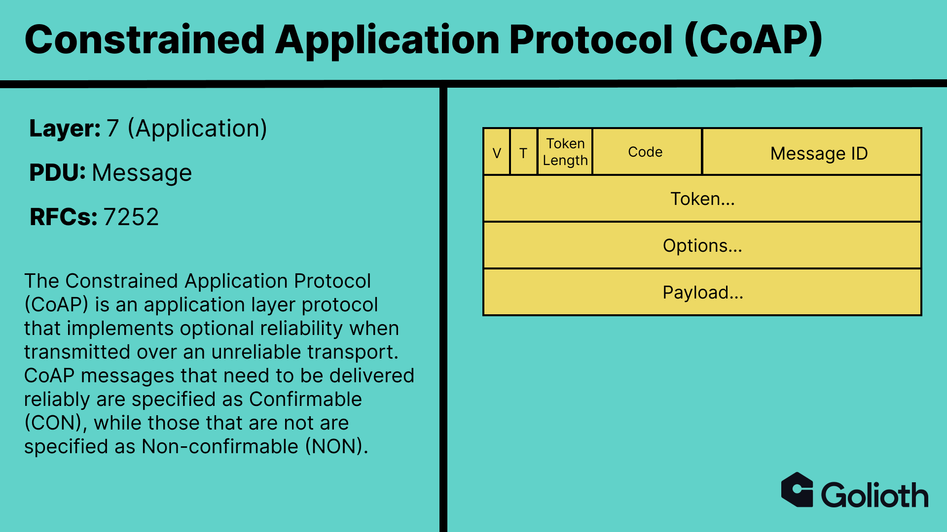
Messages are not to be confused with requests and responses. CoAP maps its request / response model to the Hypertext Transfer Protocol (HTTP), with requests providing a Method Code and responses providing a Response Code. The response to a Confirmable request message may be included in the corresponding Acknowledgement if it is immediately available. This is referred to as piggybacking. The message Token (T) is used to correlate a response to a request, meaning that when piggybacking is employed, both the request and response have the same Message ID and Token.
The log message shown above is specified as Confirmable with Message ID: 43156 and Token: 7d5b825d. The method code specifies that the request is a POST (2) , while the options specify the logs URI path and that the payload is JSON data.
Golioth should respond to this message with an Acknowledgement with a corresponding Message ID.
Not only does it do so, but it also employs piggybacking to supply a response Code (2.03 Valid (67)) and a Token matching that of the request.
How Does It Stack Up?
Though we steered clear of the data link and physical layers in this post, there is a whole world of hidden complexity yet to be uncovered beneath IP packets. The tooling and processes utilized in this post will enable both the exploration of those lower level protocols, as well as comparison between CoAP / DTLS / UDP / IP with other L3-L7 stacks. Check back for upcoming posts evaluating the similarities and differences with MQTT, QUIC, and more!
While you wait, create an account on Golioth and get your devices talking to the cloud! And if you feel so inclined, break out Wireshark and see what else you can learn.




No comments yet! Start the discussion at forum.golioth.io