At Golioth, we talk about 3 things that make for likely hardware/firmware compatibility with our Cloud:
- Running Zephyr RTOS
- Have sufficient overhead to run the Golioth code in conjunction with other Zephyr code (about 2K extra code space)
- A network interface in Zephyr
(this is not the only way to connect, just a good formula for getting started)
It’s that last point that disqualifies a bunch of boards in Zephyr. Maybe you love the STM32 feature set, but your board doesn’t have a modem to get to the internet. What then?
The great thing about Zephyr is that network interfaces are often abstracted to the point that you can add one after the fact to your board, say with a wire harness to a different PCB. If you’re at the design phase, you could also add the ESP32 as a co-processor to add connectivity. We have shown this in the past with Ethernet and with WiFi, and we’re working on a sample that adds a non-native cellular modem.
This article will show how to add WiFi to your Zephyr project in a cheap and efficient manner, using a $5 ESP32 board put into ESP-AT mode. Your project instantly has network connectivity (and a few other tricks too!).
AT commands? Like on my brick phone?
We’ll talk about the hardware in a bit, but the software part of this hinges on communication between processors using the ESP-AT command set.
AT Commands?? Like from the 80s?
Actually, exactly like that. And not just from your brick phone, the Hayes Command Set was created in 1981 for a 300 baud modem. It has survived 40 years later due to the easy connection over a serial interface (UART), which makes boards-to-board or chip-to-chip connectivity well understood and almost universally available. In fact, many of the cellular modems on the market if not using AT command sets directly (it has an ETSI standard), at least have an “AT mode” for setting up communications with cellular towers and troubleshooting.
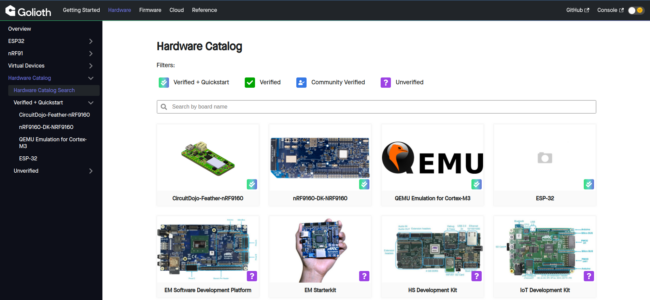
The benefit is that the ESP32 acting as a secondary processor means a wide range of parts can talk over the UART interface. Though we’re talking about Zephyr in this post, a previous example showed a Cortex-m0+ running our Arduino SDK in conjunction with the ESP32 modem. On the Zephyr side of things, you can view the wide range of boards that are supported on our hardware catalog, including boards as powerful as the Altera Max 10 FPGA board and as small as the Seeeduino XIAO.
Set up the modem
The ESP32 AT command firmware is just a binary. If you find the proper module and chipset, you should be able to download it directly onto your board. The board the ESP32 module is mounted on doesn’t really matter, as long as you have access to the pins and can tell which pin on the PCB routes back to which pin on the module.
In this example, we are working with the ESP32-WROOM-32. This is one of the most common modules on the market today. You can find which module you have by looking at the laser etching on the metal can on the module itself.
I downloaded the latest binaries (V2.2.0.0 as of this writing) from the Espressif site. I will also show the command below using that version number, though you should use the newest version that is available. There is also a page that lists the different type of binaries and the associated pin numbers you’ll need to connect to when testing below.
esptool.py write_flash --verify 0x0 ~/Downloads/ESP32-WROOM-32-V2.2.0.0/factory/factory_WROOM-32.bin
Testing the modem
Once you have successfully programmed the modem, you’ll want to test it. This will involve manually typing in AT commands to a serial interface / terminal. While that might seem like an inefficient way to work with a modem, it’s a good skill set to have if you need to troubleshoot your setup at a later time.
You will need a USB to serial converter, or some other way to communicate with a UART. These are available on Amazon for $5 or less. You do not need any fancy features on this device.
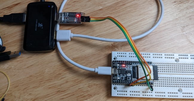
If you’re using the ESP32-WROOM32 like me, you’ll have a setup like above. Hook up your USB to serial converter TX pin to pin 16 (ESP32 RX) and the converter’s RX pin to pin 17 (ESP32 TX). Note that there are pins labeled TX and RX on the dev kit, but those are the console output for the processor. The easy way to test is if you hit the Reset button (labeled “EN” on this board), you will see all of the boot sequence scrolling across the screen if hooked into TX/RX. If you are connected to the proper output (16/17), you will only see a ready prompt when the board is booted. Reminder to check the pin numbers if you’re using a different module than above.
In terms of the program to connect you to the USB to serial and communicate with the ESP32, a small warning about line endings. After initially using screen on Linux, I found that the line endings were not compatible with the ESP-AT family. I could see the ready prompt, but I could not enter any data. After some digging I found that you need to be able to send a Carriage Return / CR (\r) and a Line Feed / LF (\n). I followed this advice and downloaded and installed picocom and used the following command on the command line to launch a more interactive terminal: picocom /dev/ttyUSB0 --baud 115200 --omap crcrlf
This enabled me to try out various commands in the ESP-AT Command Set. Two in particular stood out to me as interesting, even though they are not implemented below:
- AT+SLEEPWKCFG – Allows you to set the “light sleep” command for the modem and tell the modem which pin will be used for waking the modem.
- AT+BLEGATTSSETATTR – This sets the GATT profile for the modem in Bluetooth LE mode. The command is actually just one of many commands…I didn’t realize that it was also possible to use the modem as a Bluetooth LE gateway as well!
Use the modem with samples
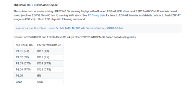
One hardware combination that is well supported in Golioth samples is the nRF52840 and the ESP32. Our “Hello” sample shows how you can configure the device and compile firmware for the nRF52840 while still taking advantage of the ESP-AT modem connected to it.
If you don’t have the nRF52840DK (Developer Kit), there are a range of other boards that will work. When you start actually running the demo, it will be very similar to our getting started using the ESP32 (natively), or the nRF9160. Our goal is to make a seamless experience once you have a network connection. We always love discussing projects in our forum, our Discord, and on Twitter.
No comments yet! Start the discussion at forum.golioth.io