We’re huge fans of Zephyr around here. We have been targeting the popular RTOS and Ecosystem since the start of Golioth, including our latest Firmware SDK release (0.15.0). And while I’ve been here a good chunk of that time, my background is in hardware and I still struggle with some simple things in Zephyr. So I thought I’d write about one of them.
Let’s start with a gripe: There is no “GPIO” example in Zephyr.
What’s that, you say? There’s a blinky example? That’s correct! The blinky example is the canonical starting point for all Zephyr dev boards and is arguably one of the simplest samples. And this does indeed utilize GPIO to turn LEDs on and off! So let’s go look at the blinky example before we get back to my gripe.
The Blinky Example
From the Zephyr docs page for the blinky sample, it tells you to build for something like the Reel Board using this command:
west build -b reel_board samples/basic/blinky
west flash
A bit further down the page, you see that you need to have an overlay file (or a native node) for your device tree to contain the following:
/ {
     aliases {
             led0 = &myled0;
     };

     leds {
             compatible = "gpio-leds";
             myled0: led_0 {
                     gpios = <&gpio0 13 GPIO_ACTIVE_LOW>;
             };
     };
};
Inner hardware engineer dialog: “What the heck am I looking at right now?”
Overlay Files and DeviceTree
I’ll pause here and quickly point you at some resources. When I was getting started, I found this to be one of the most confusing parts of Zephyr. Ultimately I know that I am going to solder a part down to the board and that there’s a physical pin that the signals will squirt out of. Depending on the IDE or Ecosystem I’m using, there might be a configurator tool, or a config file, or a set of registers I need to decode in order to get a pin to do what I want. P0.13 on the nRF52840 of the Reel Board (as shown in the example above) is going to be blinking an LED on and off and, so I want to set that…but how?
Zephyr has a “DeviceTree” that represents the nodes of a particular chip or board. When we’re trying to blink an LED on or off, we will be writing code that searches through that element to find compatible elements, such as gpio-leds. When we write code that will control the LEDs, it will know to apply the data structures we create to the LED elements. If you’re new to DeviceTree, I suggest you don’t travel too far down the rabbit hole at the beginning of your journey (but you’ll get there).
Now, this is a far cry from the experience of many hardware engineers. My earliest control of microcontrollers involved OR’ing logic that basically directly sets and LED by toggling a bit on a memory mapped register. But there are benefits to these new ways! We can have similar code target a wider range of hardware. In fact, the overlay file shown above is just that: we’re only assigning one of the pins to change from its default behavior to instead have different behavior and be mapped as gpio-leds. Another benefit is that we’re building on top of many (many!) default configurations. So in the example above, we’re actually using the reel_board board configuration that is “in-tree” in Zephyr. That is actually built on top of the nrf52840 SOC configuration, also “in-tree”. The overlay is only telling the build system what is going to change. If you’d like to see more about Overlays, one of our most popular posts on the blog is about that very topic.
One important topic is understanding how different files are pieced together when you’re building your project. There are multiple layers of inheritance that includes things like SOC definition, board definition, project configurations, and more. This will be the basis of many of your errors and build problems, especially if you start building custom hardware and firmware. My co-worker Mike always calls out that you should look at the generated devicetree files during builds (even failed ones) in order to suss out what’s wrong. This is great advice.
All the devicetree files (including your overlay files) get combined into one build/zephyr/zephyr.dts file at build time.
But what about a GPIO example?
OK, back to my gripe: There is not a GPIO example in Zephyr.
This results in many projects using gpio-leds as their representation of GPIO. Someone is triggering the pin to the enable a chip on their board and it’s still…an LED? Why is that?
Other times you’ll see someone looking to interrupt a chip with another chip and they use a callback and the button compatible type. That’s not a button!
Oh I’m guilty of it too. On my post where I was driving input of a BJT with a PWM signal to trigger a buzzer I’m also using pwm-leds? What gives?
Bindings
All of the above compatible elements are called “bindings“. This is how the system knows that when I call out pin P0.13 as an LED GPIO, I can assign a struct that matches that type of GPIO and then trigger it accordingly. On the blinky example the top line showcases how that struct is assigned:
static const struct gpio_dt_spec led = GPIO_DT_SPEC_GET(LED0_NODE, gpios);

int main(void)
{
    int ret;

    if (!gpio_is_ready_dt(&led)) {
        return 0;
    }

    ret = gpio_pin_configure_dt(&led, GPIO_OUTPUT_ACTIVE);
    if (ret < 0) {
        return 0;
    }

    while (1) {
        ret = gpio_pin_toggle_dt(&led);
        if (ret < 0) {
            return 0;
        }
        k_msleep(SLEEP_TIME_MS);
    }
    return 0;
}
In this we’re searching the device tree to find LED0_NODE and then pulling that information through to associate the GPIO with the code we’re going to write in the main loop. Note the functions used in the blinky code are not the only way to configure and trigger a GPIO.
In this case we’re using the gpio-leds binding, which as I said, is often co-opted for hardware that isn’t controlling LEDs. This is not the only type of GPIO that is available though. Zephyr expects that you will make a custom GPIO type for your project, which is why there isn’t a generic GPIO example.
The custom_dts_binding Sample
I’ll be honest, I’m really not a fan that one of the “basic” samples in Zephyr is to start making custom types of GPIO. But I kind of get it. The Zephyr project has all types of people and projects walking through the door on a daily basis. So, we’re going to make a custom devicetree binding. Ultimately it isn’t that hard, but it leans on inheritance again. The custom_dts_binding sample shows the following files (as viewed in my VS Code)
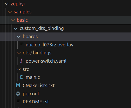
In this case nucleo_l073rz.overlay is going to call out this new binding and power-switch.yaml is the actual binding itself. The code inside that yaml is…simple!
description: GPIO pin to switch a power output on or off

compatible: "power-switch"

properties:
  gpios:
    type: phandle-array
    required: true
    description: |
      The GPIO connected to the gate driver for the MOSFET.
All it does is create a single GPIO! But now it’s a custom GPIO type. If we look at the overlay file, it calls out that compatible to match.
/ {
    load_switch: load_switch {
        compatible = "power-switch";
                /* using built-in LED pin for demonstration */
        gpios = <&gpioa 5 GPIO_ACTIVE_HIGH>;
    };
};
And now GPIO A5 is assigned to that one type of new pin. The GPIO types were hiding in plain sight.
OK, but I actually had to learn this for my own uses. I was trying to assign two GPIOs to control the pins on a programmable gain amplifier. If I tried to use the above binding (really mis-using it because it wouldn’t be for a power-switch), I wouldn’t be able to assign two pins because it’s only made for one. It’s called a ‘parent’ node.
Instead, I went and copied the devicetree binding for our old friend gpio-leds and renamed that:
description: GPIO pins to control gain on the INA225

compatible: "ina225-gain"

child-binding:
  description: The GPIOs controlling the pins for gain
  properties:
    gpios:
     type: phandle-array
     required: true
    label:
      type: string
      description: |
        Human readable string describing the LED. It can be used by an
        application to identify this LED or to retrieve its number/index
        (i.e. child node number) on the parent device.
As I’m copying this over to the blog post, I even notice I forgot to change the ‘description’ to match. Yeah, I should (and will) change that.
This allowed me to add the following to my overlay file (among many other nodes):
gain-pins {
    compatible = "ina225-gain";
    gs0: gs0 {
        gpios = <&gpio0 31 0>;
        label = "GS0 pin for INA225";
    };
    gs1: gs1 {
        gpios = <&gpio0 30 0>;
        label = "GS1 pin for INA225";
    };


};

aliases {
    gs0 = &gs0;
    gs1 = &gs1;
};
Notice that like the gpio-leds, I have multiple children elements (thanks to the child-binding) that I can name and then search later. I could have also set up two custom bindings for gs0 and gs1, but that seems like unnecessary duplication of effort.
I added ‘aliases’ so I had an easy way to search the device tree from the code in my application:
static const struct gpio_dt_spec ina225_gs0 = GPIO_DT_SPEC_GET(DT_ALIAS(gs0), gpios);
static const struct gpio_dt_spec ina225_gs1 = GPIO_DT_SPEC_GET(DT_ALIAS(gs1), gpios);
And then further down main.c
err = gpio_pin_configure_dt(&ina225_gs0, GPIO_OUTPUT_HIGH);
if (err) {
    LOG_ERR("Unable to set ina225_gs0 high");
}

err = gpio_pin_configure_dt(&ina225_gs1, GPIO_OUTPUT_HIGH);
if (err) {
    LOG_ERR("Unable to set ina225_gs1 high");
}
Since I actually only needed to have these pins be high all the time, I didn’t need to do anything else, I simply configured them at boot and left them on for the duration of my program.
Notice that the files live in the application I’m building (repeating the image here from above):
When the build system is crawling this application, it sees that there are files in dts/bindings that are custom and which will be added to the other bindings that are already in-tree in Zephyr. Same goes for the boards directory, which contains the overlays. CMakeLists.txt doesn’t need to change unless we’re adding additional files to compile in the src folder.
Aspiring Firmware Engineer
I’ve been saying for the past few years that I’m an “aspiring firmware engineer” because it’s hard to be a hardware engineer without the code to control all this silicon. I think it’s worthwhile to climb up the learning curve and take on new challenges in Zephyr. GPIO is one of many topics that will be part of that curve. As you build your skills, you’ll start to recognize more patterns and reduce your confusion during firmware build. Then you get to take advantage of all the great open source firmware that has been written by the community and you’ll accelerate your next IoT project.
If you’re having problems with this or other Zephyr topics, be sure to stop by our forum!

No comments yet! Start the discussion at forum.golioth.io