How full is your battery? How much current is your USB device drawing? What is your energy usage of your bank of devices?
Gaining granular feedback on your electricity usage is a valuable tool. We have previously discussed this as part of our AC Power Monitor. We took that concept and extended it for DC Power Monitoring. The changes were surprisingly simple, but open up a whole world of new applications.
DC Power Monitor vs AC Power Monitor
Because there are so many similarities between these reference designs, we thought it would be useful to compare and contrast. We’ll talk about some of the differences implemented below, but first off, a quick discussion about differences in how we measure power.
In AC Power Monitoring, it’s “non-contact”. The power passing through AC wires can get up to considerable amounts, and often we don’t want to measure this “in line”. Also, it’s often not a requirement to have precise measurement levels. In both of these scenarios, we can get away with using a current clamp, which uses the magnetic fields around a wire to induce a reference current, and then couples that reference into a secondary measurement circuit.
DC Power doesn’t have the same characteristics. Though there is a magnetic field that develops around a wire, the non-alternating nature of DC current means it is not possible to stimulate a current in the secondary of a measurement circuit using an inductive element. Instead, we need to measure current “in-line”, which means the current we’re measuring passes through a resistive element and we measure the voltage that develops across that resistor. The benefit is we can measure much lower current and get better resolution. This is what we were doing when we did a webinar about measuring power consumption of cellular in different modes. Now we’re taking that same idea and scaling it up for higher current devices like battery charging or measuring power consumption of a USB device.
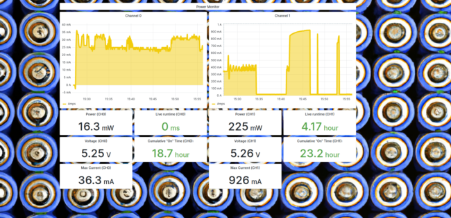
In both designs, two channels stream readings back to Golioth where they are stored along with their timestamp. The power monitor tracks “run” time—how long the device being monitored has been running without a break. The system also records the cumulative “run” time so that you can track the service life of your equipment. This data is invaluable in planning maintenance and identifying the most used equipment to inform future investment in your production abilities.
Hardware
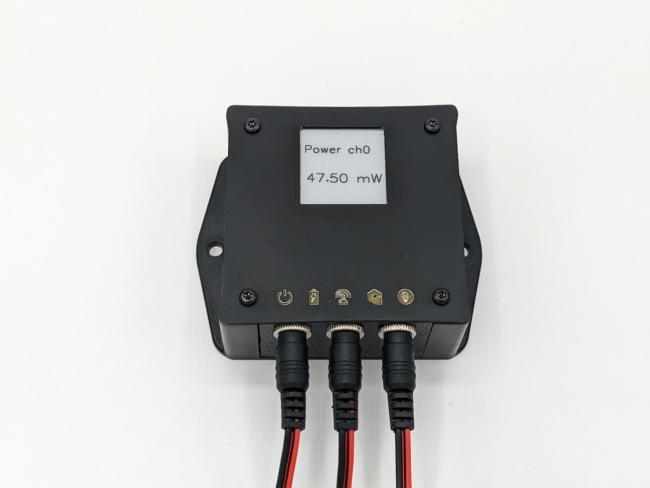
We were mostly swapping out Click headers when we converted this from an AC measurement device to a DC measurement device. We also added a new “quick disconnect” cabling setup to make it easier to transport demos to conferences.
The full parts list is on our Golioth Projects page, but the new element used to measure current “in-line” is the MikroElectronika VCP Click, which is based around the INA260AIPWR from Texas Instruments. The datasheet calls out a range of target applications, which could be rich areas to target with this overall reference design:
- Test Equipment
- Servers
- Telecom Equipment
- Computing
- Power Management
- Battery Chargers
- Power Supplies
This class of chip is well suited to measure DC power and includes a voltage measurement circuit. Since it’s on the i2c bus, retrieval of measurements is quite easy. The driver for this chip is not in-tree for Zephyr, so it came down to i2c calls from our Zephyr firmware.
The cellular modem (nRF9160) is one of our best supported parts on Golioth and is powered from both a local power supply and a lithium battery so that power outages can be remotely detected.
Firmware
The primary changeover from AC to DC power monitoring was the code to extract readings from the VCP Click, mentioned above. After that, most of the rest of the plumbing was left in place.
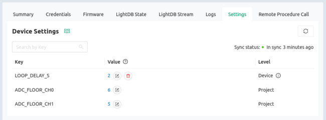
Much like the AC Power Monitor, the firmware for the Power Monitor reference design uses the Golioth Settings Service. This service can update a single device’s settings, and also provides fleet-wide control via our web console (and our REST API if you need it).

Here you can see the loop delay which indicates how long the device should sleep between sensor readings (in seconds). There is also an ADC “floor” setting available for each channel. This accommodates equipment that has some current draw when in standby mode, allowing you to configure the threshold at which the machine is consider to be running.
All of the Golioth reference designs include Over-the-Air (OTA) firmware updates. Though it was not the case when we built it, it’s feasible that we could have instructed a technician to swap out the Click headers and we could have pushed an OTA update and changed a device from AC to DC in the field. Modular hardware paired with an OTA system creates an endlessly customizable end product.
Cloud Software / Dashboard
A quick recap of the features in both the AC and DC Power Monitor designs:
- Sensor readings are stored as time-series data on LightDB Stream
- Device settings are monitored in real-time, with the device reacting to your changes as soon as you make them.
- The Golioth Console tracks the latest device state, including device health
- Current firmware version is monitored, with the ability to rollout new OTA updates, and one-click rollback if you need it
- Golioth’s convenient REST API delivers easy access to the data for visualization or export to any of your favorite cloud server platforms.
Our Grafana interface looks a little different than before, namely in the units we’re tracking (DC Power Monitor envelopes are much smaller) and the background image:
More Golioth Reference Designs
A recent refresh to the Golioth Projects page shows the range of different Reference Designs we make available for our customers. We continue to add new designs and would love to hear about application spaces we could target next. Reach out on our forum or over email if you’d like to send us suggestions. Don’t worry, we have ideas if we don’t hear from you.


No comments yet! Start the discussion at forum.golioth.io