In this post, we’ll walk through a couple methods for defining abstract hardware interfaces in Zephyr using the devicetree.
You’ve probably seen abstract hardware interfaces implemented on popular development boards. Many boards provide a standardized connector interface like mikroBUS, Feather, MicroMod, Arduino UNO, etc. A defining characteristic of these interfaces is the ability to plug in a range of peripheral boards that do different things, but still all use the same signals.
For example, a MikroE Weather Click board that implements the mikroBUS standard can be plugged into a LPCXpresso55S28 dev board or a STM32 M4 Clicker dev board without requiring any hardware changes to the Weather Click boards. The signals are always in the same place on the ClickBus form factor (even if each Click board doesn’t use all of them).
Using abstract interfaces can enable writing more portable devicetree definitions that can be reused across multiple boards.
Same app, multiple boards
We’ve been updating our collection of Golioth reference designs to support our Follow-Along Hardware boards. These are designs you can build yourself using off-the-shelf development boards.
Zephyr’s Devicetree support enables us to decouple the hardware definition for each board from the application source code. By using devicetree interfaces to the underlying hardware, we can target completely different boards (or different revisions of the same board) without any changes to the application code.
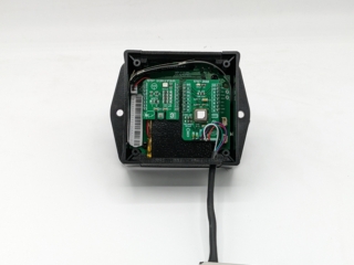
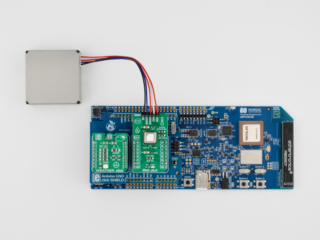
For example, the images below show two supported boards that run the same Air Quality Monitor reference design firmware:
[av_one_half first av_uid=’av-4xryr6′]
[/av_one_half]
[av_one_half av_uid=’av-22gm5e’]
[/av_one_half]
Why use abstract hardware interfaces?
Look closely at the images above. You’ll notice that both platforms are hosting the exact same MikroE Click sensor modules.
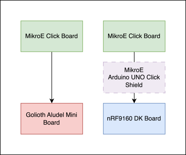
These Click modules adhere to the mikroBUS socket specification, ensuring that any Click board can be plugged into any standard mikroBUS socket:
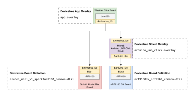
The Golioth Aludel Mini board in the left photo above includes two built-in MikroBUS sockets. The nRF9160 DK board in the right photo above uses an Arduino UNO Click shield to convert the onboard Arduino socket into two MikroBUS sockets.
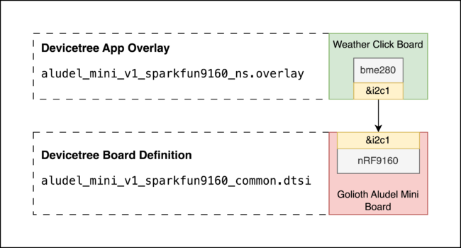
The Weather Click board we’re using in the Air Quality Monitor reference design uses the I2C interface on the mikroBUS socket to read weather data from the onboard BME280 sensor.
On our custom Golioth Aludel Mini board, the mikroBUS I2C interface is connected to the nRF9160’s I2C1 peripheral. We could describe this hardware in the application’s aludel_mini_v1_sparkfun9160_ns.overlay file like this:
&i2c1 {
	status = "okay";

	bme280: bme280@76 {
		compatible = "bosch,bme280";
		reg = <0x76>;
	};
};
However, on the off-the-shelf nRF9160 DK Follow-Along Hardware board, the mikroBUS I2C interface is connected to the nRF9160’s I2C2 peripheral (through the Arduino UNO Click shield). Similarly, we could describe this hardware in the application’s nrf9160dk_nrf9160_ns.overlay file like this:
&i2c2 {
	status = "okay";

	bme280: bme280@76 {
		compatible = "bosch,bme280";
		reg = <0x76>;
	};
};
There are a couple downsides to this approach:
- It’s not very DRY. We are repeating the same
bme280node definition in each board overlay file in the application. If we swapped out the Weather Click board for a board with a different sensor, we’d have to update each board definition individually. - It doesn’t reflect the actual hardware interface. The definitions above tightly couple the sensor hardware definitions to specific MCU peripherals on each board. As a result, we need a slightly different sensor configuration for each board.
Node labels as abstract interfaces
One simple way to address the downsides listed above is to define an abstract hardware interface using node labels.
Defining abstract hardware interfaces in boards
We can add node labels in a board’s devicetree definition for the mikroBUS UART, I2C, and SPI communication interfaces. Here’s the mikroBUS node labels for the Golioth Aludel Mini board from the aludel_mini_v1_sparkfun9160_common.dtsi file:
mikrobus_serial: &uart2 {};
mikrobus_i2c: &i2c1 {};
mikrobus_spi: &spi2 {};
Because the mikroBUS abstract interface is implemented directly by this board, these node labels map directly to specific peripherals on the nRF9160 MCU.
On the other hand, the nRF9160 DK doesn’t have any built-in mikroBUS sockets, so the nrf9160dk/nrf9160 board definition does not include these mikrobus_* node labels. However, if we enable the Arduino UNO Click shield (-DSHIELD="arduino_uno_click") when building for the nrf9160dk/nrf9160 board, the built-in arduino_uno_click.overlay will include the following mikrobus_* node labels:
mikrobus_spi: &arduino_spi {};
mikrobus_serial: &arduino_serial {};
mikrobus_i2c: &arduino_i2c {};
Since the mikroBUS abstract interface is implemented by the Arduino UNO Click shield, these node labels simply “pass through” to the arduino_* abstract interface implemented in the nrf9160dk_nrf9160_common.dtsi file.
(Currently, there is a bug with the mikrobus_i2c interface when using the arduino_uno_click shield with the nrf9160dk/nrf9160 board. See this PR for a fix.)
Using abstract hardware interfaces in overlays
Since all the boards supported by our application implement the mikrobus_* abstract interface, we can define the devicetree nodes for the Click boards in a single place using these node labels. For example, we could create a single application-level overlay app.overlay for the Weather Click board:
&mikrobus_i2c {
	status = "okay";

	bme280: bme280@76 {
		compatible = "bosch,bme280";
		reg = <0x76>;
	};
};
Using abstract hardware interfaces in Shields
We can even take this one step further and turn this app.overlay into a mikroe_weather_click Zephyr Shield that we can use across multiple apps.
First, we need to add a boards/shields/mikroe_weather_click/Kconfig.shield with the following config:
config SHIELD_MIKROE_WEATHER_CLICK
	def_bool $(shields_list_contains,mikroe_weather_click)
Next, we add a boards/shields/mikroe_weather_click/mikroe_weather_click.overlay with the same devicetree code from the app.overlay above:
&mikrobus_i2c {
	status = "okay";

	bme280_mikroe_weather_click: bme280@76 {
		compatible = "bosch,bme280";
		reg = <0x76>;
	};
};
Now we can simply include this shield overlay in any app by specifying the argument -DSHIELD="mikroe_weather_click" in the build command.
For example, to build the samples/sensor/bme280 app for the nRF9160 DK board + Arduino UNO Click shield + Weather Click shield:
west build -p -b nrf9160dk/nrf9160/ns samples/sensor/bme280 -- -DSHIELD="arduino_uno_click mikroe_weather_click"
(This PR adds the mikroe_weather_click shield to upstream Zephyr.)
GPIO Nexus Nodes
The mikroBUS interface described earlier defines a set of GPIO used for various purposes by the Click modules: SPI chip select (CS), enable (EN), reset (RST), interrupt (INT), etc. This is essentially an abstract interface for a group of GPIO pins. Any board that implements mikroBUS must map these pins on the socket to SoC-specific GPIO on the board.
So far, we’ve described how to define and use abstract interfaces via node labels. However, there is no single node in the devicetree that represents a GPIO pin. You can’t use a single phandle to represent one.
Instead, the Devicetree specification provides Nexus Nodes for creating these types of mappings. Specifically, GPIO nexus nodes provide a mapping between an abstract GPIO interface and the actual GPIO pins on a SoC.
For example, we can take a look at the mikroBUS GPIO nexus node defined for the lpcxpresso55s36 board:
mikrobus_header: mikrobus-connector {
	compatible = "mikro-bus";
	#gpio-cells = <2>;
	gpio-map-mask = <0xffffffff 0xffffffc0>;
	gpio-map-pass-thru = <0 0x3f>;
	gpio-map =	<0 0 &gpio1 9 0>,	/* AN  */
			/* Not a GPIO*/		/* RST */
			<2 0 &gpio0 20 0>,	/* CS   */
			<3 0 &gpio1 2 0>,	/* SCK  */
			<4 0 &gpio1 3 0>,	/* MISO */
			<5 0 &gpio0 26 0>,	/* MOSI */
						/* +3.3V */
						/* GND */
			<6 0 &gpio1 8 0>,	/* PWM  */
			<7 0 &gpio0 17 0>,	/* INT  */
			<8 0 &gpio1 24 0>,	/* RX   */
			<9 0 &gpio1 25 0>,	/* TX   */
			<10 0 &gpio1 30 0>,	/* SCL  */
			<11 0 &gpio1 21 0>;	/* SDA  */
						/* +5V */
						/* GND */
};
The main thing to highlight here is that the gpio-map is a mapping, where each row maps an abstract GPIO “specifier” (e.g. <&mikrobus_header 2 0>) to a real GPIO “specifier” on the LPC55S36 MCU (e.g. <&gpio0 20 0>). See the Zephyr documentation for GPIO nexus nodes and the devicetree spec for detailed descriptions of the other properties.
We can now refer to <&mikrobus_header 2 0> instead of <&gpio0 20 0> when referring to GPIOs in devices that use the mikroBUS interface. This is good because it means that we can define an app.overlay or a <shield>.overlay that is not tied to a specific SoC pin on a board.
Devicetree Aliases & Chosen Nodes
The methods we’ve shown above are helpful for defining abstract interfaces between hardware devices within devicetree. In this final section, we’ll show how to expose abstract hardware interfaces to your application via aliases & chosen nodes.
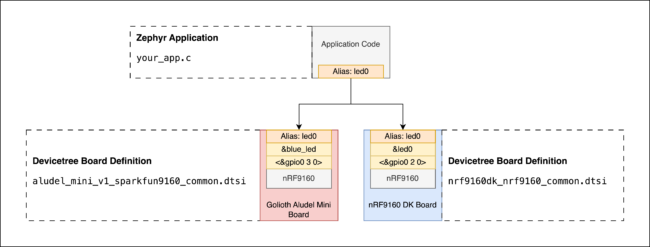
These provide a way to refer to abstract nodes without having any knowledge of the specific hardware implementation. In general, the idea is to use abstract node labels (mikrobus_i2c) to decouple devicetree definitions from board-specific devices, and use aliases/chosen nodes to decouple the application code from board-specific devices.
For example, it’s possible to build the zephyr/samples/basic/blinky app for many different boards without changing any of the application code. The only requirement is that each board’s devicetree definition must provide the board-specific implementation for the led0 alias—the abstract interface used by the application code:
leds {
	compatible = "gpio-leds";
	led0: led_0 {
		gpios = <&gpio0 2 0>;
	};
	...
};

aliases {
	led0 = &led0;
	...
};
You can access this led0 alias in your application code like this:
#define LED0_NODE DT_ALIAS(led0)

static const struct gpio_dt_spec led = GPIO_DT_SPEC_GET(LED0_NODE, gpios);
Conclusion
Devicetree stuff is never clear on the first reading, but is super logical in the long run. Hopefully this was helpful in clarifying how to define and use abstract hardware interfaces in devicetree. If you have any follow up questions or comments, feel free to reach out in our forum.
Interested in learning more about Zephyr? Then, we’d love to have you join us for a free Zephyr developer training. Our next session is coming up in May. Sign up now!



No comments yet! Start the discussion at forum.golioth.io