Opening a serial port to an embedded device is a staple of pretty much every embedded systems development process. Dev boards universally offer serial port access, often via USB. But production devices may only have test points available for TX and RX lines.
In these instances, the J-Link programmer you’re using to flash firmware to the device may also be used to access the serial port. Today I’ll show how to use your J-Link programmer to open a serial port.
VCOM is Built-Into Segger J-Link
A virtual com port is one of the built-in features of the Segger J-LInk. However, it is disabled by default. Turning the feature on is just a matter of opening J-Link Commander (eg: run JLinkExe; yes, even on Linux) and typing vcom enable.
Type "connect" to establish a target connection, '?' for help
J-Link>vcom enable
After issuing this command, power cycle your programmer by unplugging and replugging the USB cable. You will see a new com port enumerate:
[1919249.237106] usb 1-3: new high-speed USB device number 39 using xhci_hcd
[1919249.457064] usb 1-3: New USB device found, idVendor=1366, idProduct=0105, bcdDevice= 1.00
[1919249.457098] usb 1-3: New USB device strings: Mfr=1, Product=2, SerialNumber=3
[1919249.457113] usb 1-3: Product: J-Link
[1919249.457126] usb 1-3: Manufacturer: SEGGER
[1919249.457139] usb 1-3: SerialNumber: 000050109638
[1919249.483160] cdc_acm 1-3:1.0: ttyACM0: USB ACM device
Connecting to RX/TX
Now make the physical connections to your device. You need at least 4 connections: RX, TX, GND, VTref.
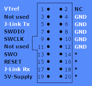
- target device TX pin connects to the J-Link RX on pin 17
- target device RX pin connects to the J-Link TX on pin 5
- VTref is the voltage level of your device
- ground is… well… ground on both programmer and target device
Once connected, you will have a serial port available on the virtual com port address we saw in the previous section. For me it’s as as easy as opening minicom:
minicom -D /dev/ttyACM0
We already have this, RTT (right)?
Another option, and one we’ve written about before, is to use RTT with a JLink. This is a true virtual COM port that gets passed over SWD lines, no external lines or UARTs required. While the lower amount of wires can be beneficial, the reliability of communication and additional binaries can be a hassle; to use RTT, you need to run a second program like JLinkRTTViewer to tap into these signals. For higher speed communication or an RTOS hopping between threads, we have seen RTT not be completely up to the task. However, we do utilize it to take advantage of other capabilities like Segger’s SystemView.
Jumper Wires and Programming Headers
Now it is possible to use the J-Link purely as a serial-to-USB bridge. But I’m guessing that if you invested in one of these indespensible-yet-costly programmers you’re actually using it for programming.
If your device is programmed via SWD, then the VCOM pins are available at the same time so you don’t need to disconnect the VCOM pins in order to flash or debug the target device. Even better, VTref and Gnd are already connected so you only need to add two wires!
If you have the ear of your hardware design engineers, see if you can get them to design with this com port in mind. Add RX/TX lines to your programming headers, whether that’s a simple SIL header or a 10-pin Tag Connect footprint. But even if you only have test points, tacking on a female DuPont-style jumper wire makes it easy to connect and disconnect your development/testing unit from the J-link.
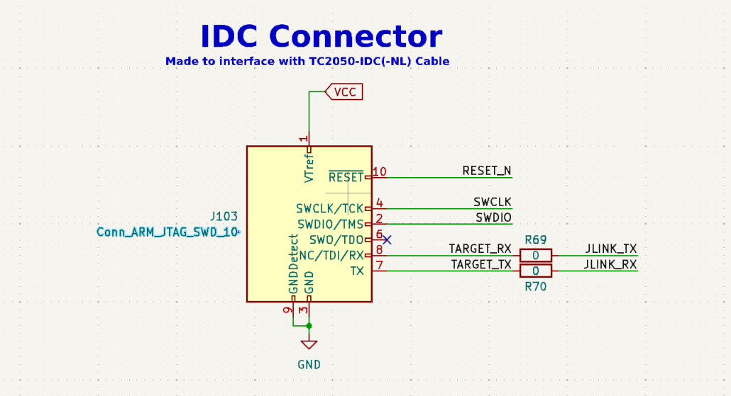
Tag Connect modification
If you add the TX/RX to a 10 pin TagConnect cable (TC2050-IDC-NL), it might look like this. In this case, we’re interfacing to an nRF52.
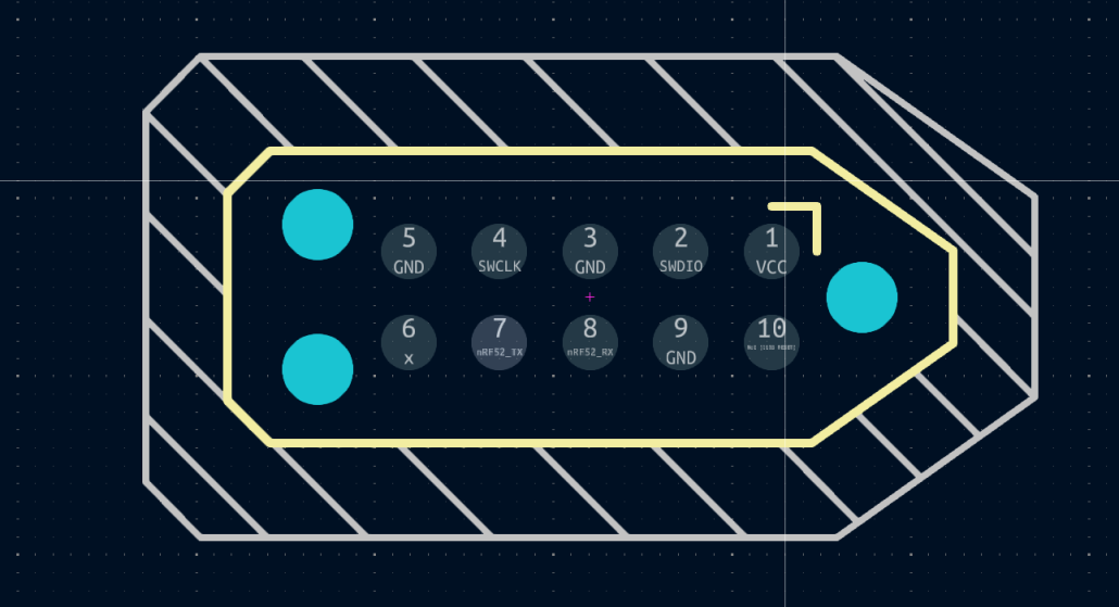
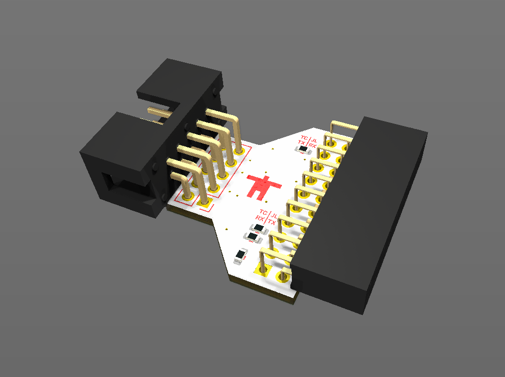
From here, we’d need to actually get those two pins off of the TagConnect cable and into a JLink for the proper pins. We pull those into a custom PCB breakout that looks like this:
If you would like the files, please let us know on our Forum!

Can you please share the design files of the adapter? Thanks
@mike can you please share the design files of the adapter? Thanks