Golioth recently received a number of customer reports regarding connectivity issues on a specific vendor’s cellular chipset series. We immediately contacted the vendor and began working towards reproducing and isolating the behavior. What ensued was a lengthy investigation that ultimately revealed some unexpected and highly undesirable behavior. This is a story of the complexities of cellular connectivity, the perils of closed ecosystems, and how to debug what you cannot see.
We previously posted on the Golioth forum with a description of this issue and potential workarounds.
To Live is to Be Connected
Before going into detail about the sad state of affairs that is the telecommunications industry, it is important to provide some context around why connectivity is so important for large fleets of devices. Sure, it can be frustrating when your phone or laptop is unable to access the internet. Whether it is because your internet service provider (ISP) is having an outage, there is a bug in your device’s network stack, or any other issue, you may not be able to complete essential tasks. However, you can call your ISP, go to a coffee shop and use their Wi-Fi to download a software update, or execute the tried and true “turn it off then turn it back on” strategy. While the lack of connectivity is not convenient for personal devices, it usually is temporary and does not render the device permanently useless.
The same cannot be said for large fleets of devices deployed in hard-to-access locations. Connection failures that require physical intervention can be fatal for a device, as it might be literally inaccessible, or the cost of accessing it may be so exorbitant that it might as well be. Because of this, we, and our customers, go to great lengths to ensure that devices that fail to connect are able to recover gracefully.
For example, Golioth’s Over-the-Air (OTA) firmware update implementation integrates with recommended frameworks for each supported platform, such as mcuboot and esp-idf OTA, to ensure that a deployed firmware update is able to be rolled back in the case of failure to connect. When a firmware update is initiated via the Golioth cloud platform, devices in the field that are currently connected are notified that a new image is available, and those that are not are notified on next connection. The device will then download the new image into flash in a secondary or “candidate” partition. If download and image verification is successful, the device will subsequently mark the new image as the boot image in a “test” mode, then reboot into it. If there is a crash after reboot or the device is unable to connect for a configurable time window, the device will swap the previous image back, reboot, and continue operation as before.
Signs of Trouble
Initial reports regarding connectivity issues with the nRF9160 centered around devices that had recently performed OTA firmware updates. It manifested as some devices in a cohort targeted by a deployment successfully downloading the new firmware image, starting an update, then eventually rolling back to a previous version. While this would typically indicate an issue in the new firmware image, it appeared to only be impacting a subset of devices in the cohort. Furthermore, a number of the devices eventually successfully updated to the new image after a handful of retries.
There are three broad categories of issues one can encounter when working with devices on a cellular connection:
- Firmware
- Connectivity
- Cloud
We like firmware and cloud issues because they are domains that we and our customers can, for the most part, control. If something is going wrong on either side of a connection we are typically able to track down and resolve the issue using observability and debugging tooling. Given the correlation of the nRF9160 connectivity issues with recent firmware updates, our immediate inclination was that customers had updated to the latest version of the Golioth Firmware SDK (v0.17.0) and there had been a regression either in our SDK or one of the platform versions it pins (i.e. nRF Connect SDK, Zephyr). However, reports indicated that multiple versions of both our SDK and the nRF Connect SDK were exhibiting the issue.
We started out by attempting to reproduce the behavior using v0.17.0. The nRF9160 development kit is one of our continuously verified boards, meaning that we are constantly running continuous integration tests on it via our hardware-in-the-loop (HIL) infrastructure. In fact, the history of firmware update test statuses for the nRF9160DK are available on our public dashboard. However, after running a large number of firmware updates across a variety of geographic locations, we observed an issue that exhibited in a manner similar to the received reports. After downloading a new firmware image, devices would report an inability to resolve the coap.golioth.io domain name to an address, then subsequently rollback to the previous image.
[00:01:40.747,802] <err> golioth_coap_client_zephyr: Fail to get address (coap.golioth.io 5684) -2
[00:01:40.747,802] <err> golioth_coap_client_zephyr: Failed to connect: -11
[00:01:40.747,802] <wrn> golioth_coap_client_zephyr: Failed to connect: -11
[00:01:45.756,652] <err> golioth_coap_client_zephyr: Fail to get address (coap.golioth.io 5684) -2
[00:01:45.756,683] <err> golioth_coap_client_zephyr: Failed to connect: -11
[00:01:45.756,683] <wrn> golioth_coap_client_zephyr: Failed to connect: -11
[00:01:50.765,533] <err> golioth_coap_client_zephyr: Fail to get address (coap.golioth.io 5684) -2
[00:01:50.765,563] <err> golioth_coap_client_zephyr: Failed to connect: -11
[00:01:50.765,563] <wrn> golioth_coap_client_zephyr: Failed to connect: -11
Unfortunately, the behavior was intermittent, and upon testing older versions of our SDK and the nRF Connect SDK, we were still able to observe the behavior seemingly at random after a reboot, whether updating to a new firmware image or not. Even more confounding, when using the Zephyr network shell to manually issue a DNS request, the resolution was successful…on the same device… while it was reporting DNS failures.
[01:42:28.365,356] <err> golioth_coap_client_zephyr: Fail to get address (coap.golioth.io 5684) -2
[01:42:28.365,386] <err> golioth_coap_client_zephyr: Failed to connect: -11
[01:42:28.365,417] <wrn> golioth_coap_client_zephyr: Failed to connect: -11
uart:~$ net dns coap.golioth.io
Query for 'coap.golioth.io' sent.
dns: 34.135.90.112
dns: All results received
[01:42:33.365,875] <err> golioth_coap_client_zephyr: Fail to get address (coap.golioth.io 5684) -2
[01:42:33.365,905] <err> golioth_coap_client_zephyr: Failed to connect: -11
[01:42:33.365,936] <wrn> golioth_coap_client_zephyr: Failed to connect: -11
When I said there were three broad categories of issues with cellular devices, I probably should have split the first, firmware, into two separate domains. We like solving problems in the application domain, but a large portion of the firmware running on a cellular device resides in the modem.
Secret Handshakes and Back Alleys
In some cases, there is some limited access to firmware on a modem. For example, we recently announced support for running Golioth on modem processors. However, even when limited access is available, it typically depends upon encrypted binary blobs, new versions of which are distributed at the whim of the silicon vendor. The nRF9160 modem falls into the category of lesser access, though we are fortunate enough to be blessed with moderately detailed release notes when a new firmware version is available.
But before you go egging the Nordic Semiconductor headquarters, consider the fact that they are one of the most open vendors in the industry. They invest heavily in the Zephyr RTOS ecosystem, open source the vast majority of their SDK, provide better developer tooling than their competitors, and are generally fairly responsive on their public forums. Let this blog post not be a slandering of their fine handiwork.
No, Nordic is merely a participant in a vast ecosystem that convenes via the 3rd Generation Partnership Project, or 3GPP as it’s known among friends. 3GPP was formed in 1998 out of the joining of seven different standards organizations — queue the xkcd meme. 3GPP develops the standards that underpin all wireless communication in the world today. These technical specifications (TS) are aggregated and included in “releases”, which are made freely available. Unfortunately, much of the technology that is required to implement the standards is patented. The patents are referred to as Standards Essential Patents, or SEPs. Because of this arrangement, a vendor like Nordic probably can’t open source their modem firmware even if they wanted to.
Nevertheless, if some brave soul was willing to painstakingly navigate the deluge of 3GPP specifications, they would be able to get an idea of what a modem and the cellular networks it connects to should be doing by reading through the hundreds of documents. In the case of the nRF9160, the primary specifications of interest would be part of 3GPP Release 13, which introduced LTE Cat-M1 (eMTC) and NB-IoT.
Figuring Out What Is Going On
Prior to my divergence into the morass of intellectual property that provides the foundation of wireless communication, we had just observed that DNS requests were successful when issued via the Zephyr network shell. That felt like a good place to probe deeper, given that we clearly had an internet connection and were simply unable to use it.
The firmware used for testing was the Zephyr fw_update example in the Golioth Firmware SDK. The Golioth Zephyr CoAP client implementation uses zsock_getaddrinfo to resolve the server domain name (coap.golioth.io) to an IP address.
ret = zsock_getaddrinfo(host, port, &hints, &addrs);
if (ret < 0)
{
    LOG_ERR("Fail to get address (%s %s) %d", host, port, ret);
    return -EAGAIN;
}
We could see the error log emitted on failure in the output of our reproduction. When using nRF91 series devices, socket offloading must be enabled for LTE connectivity. This results in the creation of an offloaded network interface and binds it to the nrf9x_socket device.
static struct offloaded_if_api nrf9x_iface_offload_api = {
    .iface_api.init = nrf9x_iface_api_init,
    .enable = nrf9x_iface_enable,
};

/* Actual MTU for the nRF9x LTE link is handled by `lte_net_if.c` */
NET_DEVICE_OFFLOAD_INIT(nrf9x_socket, "nrf9x_socket",
            nrf9x_socket_offload_init,
            NULL,
            &nrf9x_iface_data, NULL,
            0, &nrf9x_iface_offload_api, 1280);
The initialization function then calls socket_offload_dns_register, to setup the corresponding offload implementations for getaddrinfo and freeaddrinfo.
static const struct socket_dns_offload nrf9x_socket_dns_offload_ops = {
    .getaddrinfo = nrf9x_socket_offload_getaddrinfo,
    .freeaddrinfo = nrf9x_socket_offload_freeaddrinfo,
};

static struct nrf9x_iface_data {
    struct net_if *iface;
} nrf9x_iface_data;

static void nrf9x_iface_api_init(struct net_if *iface)
{
    nrf9x_iface_data.iface = iface;

    iface->if_dev->socket_offload = nrf9x_socket_create;

    socket_offload_dns_register(&nrf9x_socket_dns_offload_ops);

    if (!IS_ENABLED(CONFIG_NRF_MODEM_LIB_NET_IF_AUTO_START)) {
        net_if_flag_set(iface, NET_IF_NO_AUTO_START);
    }
}
The former ultimately calls nrf_getaddrinfo, which is provided by the binary modem library distributed by Nordic. This is not the modem firmware, but rather the interface from the application processor to the modem firmware. This is ultimately where the error on the application processor originates, but the issue is only being propagated from the modem. At this point we turned our attention to the net dns handler in the network shell, which appeared to be communicating with the modem via another mechanism. Sure enough, following the call stack from cmd_net_dns_query revealed a call to zsock_sendto, notably with the server address provided.
ret = zsock_sendto(sock, buf, len, 0, server, server_addr_len);
The implementation is defined in the offloaded sockets vtable.
static const struct socket_op_vtable nrf9x_socket_fd_op_vtable = {
    .fd_vtable = {
        .read = nrf9x_socket_offload_read,
        .write = nrf9x_socket_offload_write,
        .close = nrf9x_socket_offload_close,
        .ioctl = nrf9x_socket_offload_ioctl,
    },
    .bind = nrf9x_socket_offload_bind,
    .connect = nrf9x_socket_offload_connect,
    .listen = nrf9x_socket_offload_listen,
    .accept = nrf9x_socket_offload_accept,
    .sendto = nrf9x_socket_offload_sendto,
    .sendmsg = nrf9x_socket_offload_sendmsg,
    .recvfrom = nrf9x_socket_offload_recvfrom,
    .getsockopt = nrf9x_socket_offload_getsockopt,
    .setsockopt = nrf9x_socket_offload_setsockopt,
};
nrf9x_socket_offload_sendto then calls nrf_sendto, which takes us back into the binary modem library. The key difference between these paths is that the former asks the modem to perform a DNS request on its behalf, while in the latter, the DNS request is formed, then the modem is asked to send the request to the specified server. In this case, the server happens to be Cloudflare’s 1.1.1.1 , which is set as the default in the Golioth Firmware SDK for Zephyr examples.
At this point, we considered whether there could be a bug in the modem firmware. We had already reached out Nordic, but we needed to move quickly to address the issue. Unfortunately, we were unable to disassemble the encrypted modem firmware binary that Nordic distributes, and dumping the unencrypted firmware proved difficult. We quickly tested a few different versions of the modem firmware to ensure that the behavior had not been corrected in a newer version. The issue reproduced intermittently across all of them.
Perhaps there was an issue with the DNS server used by the modem? This raised the question of how the modem was deciding upon a DNS server to use in the first place. We discovered the nrf_setdnsaddr function in the modem library, which provided some interesting documentation.
/**
 * @brief Set a secondary DNS address.
 *
 * @details
 * The secondary DNS address is only used in case the primary DNS address is unreachable,
 * or if no DNS address is provided by the operator. The secondary DNS address does not
 * override the primary DNS address.
It was still unclear as to how the primary DNS server address was being set, but we figured calling the function prior to attempting DNS resolution was worth a shot.
struct nrf_in_addr dns;
dns.s_addr = 16843009;  // Cloudflare DNS, 1.1.1.1
nrf_setdnsaddr(NRF_AF_INET, &dns, sizeof(dns));
LOG_INF("manually set DNS server via nrf_setdnsaddr");
Maddeningly, it worked. Given the behavior was intermittent, we made sure to test repeatedly, but the device connected every time. Suddenly we had the only thing worse than no solution: a solution that you don’t understand. Hardly comfortable recommending this as a generic workaround to our customers, our pursuit continued.
Curious as to what the modem considered its primary and secondary DNS server addresses, we began pouring through the AT commands supported by the nRF91 series. The PDN connection dynamic parameters (AT+CGCONTRDP) command returns information about an active Packet Data Network (PDN) connection, including fields described as primary and secondary DNS. After removing the nrf_setdnsaddr call, we added the following immediately after successful LTE registration.
err = nrf_modem_at_cmd(at_resp, sizeof(at_resp), "AT+CGCONTRDP=0");
if (err)
{
    LOG_WRN("nrf_modem_at_cmd failed. errno: %d", err);
    return -1;
}
LOG_INF("%s", at_resp);
The first test was successful and revealed 8.8.8.8 and 8.8.4.4 as primary and secondary DNS servers respectively.
[00:00:00.510,864] <dbg> fw_update_sample: main: Start FW Update sample
[00:00:00.510,894] <inf> golioth_samples: Bringing up network interface
[00:00:00.510,894] <inf> golioth_samples: Waiting to obtain IP address
[00:00:10.049,316] <inf> lte_monitor: Network: Searching
[00:00:11.140,258] <wrn> lte_lc: Registration rejected, EMM cause: 15, Cell ID: 39848451, Tracking area: 39680, LTE mode: 7
[00:00:15.617,614] <inf> lte_monitor: Network: Registered (roaming)
[00:00:15.618,591] <inf> fw_update_sample: +CGCONTRDP: 0,,"hologram","","","8.8.8.8","8.8.4.4"
[00:00:15.848,937] <inf> golioth_mbox: Mbox created, bufsize: 1232, num_items: 10, item_size: 112
[00:00:15.849,731] <inf> golioth_fw_update: Current firmware version: main - 0.0.8
[00:00:15.851,470] <inf> golioth_fw_update: State = Idle
[00:00:17.516,204] <inf> golioth_coap_client_zephyr: Golioth CoAP client connected
[00:00:17.516,479] <inf> fw_update_sample: Golioth client connected
However, on a subsequent failed test, the first indication of the root cause appeared.
[00:01:03.706,878] <inf> lte_monitor: Network: Registered (roaming)
[00:01:03.707,672] <inf> fw_update_sample: +CGCONTRDP: 0,,"hologram","",""
[00:01:03.708,526] <inf> golioth_mbox: Mbox created, bufsize: 1232, num_items: 10, item_size: 112
[00:01:03.709,320] <inf> golioth_fw_update: Current firmware version: main - 0.0.8
[00:01:03.711,059] <inf> golioth_fw_update: State = Idle
[00:01:03.711,639] <err> golioth_coap_client_zephyr: Fail to get address (coap.golioth.io 5684) -2
[00:01:03.711,669] <err> golioth_coap_client_zephyr: Failed to connect: -11
[00:01:03.711,669] <wrn> golioth_coap_client_zephyr: Failed to connect: -11
The DNS server addresses were missing! After re-adding nrf_setdnsaddr, then invoking AT+CGCONTRDP both before and after calling it, both the primary and secondary appeared to be missing intermittently, but the subsequent DNS resolution was always successful.
[00:00:41.886,840] <inf> lte_monitor: Network: Registered (roaming)
[00:00:41.892,913] <inf> fw_update_sample: +CGCONTRDP: 0,,"hologram","",""
[00:00:41.895,119] <inf> fw_update_sample: manually set DNS server via nrf_setdnsaddr
[00:00:41.899,688] <inf> fw_update_sample: +CGCONTRDP: 0,,"hologram","",""
[00:00:42.950,469] <inf> golioth_mbox: Mbox created, bufsize: 1232, num_items: 10, item_size: 112
[00:00:42.951,263] <inf> golioth_fw_update: Current firmware version: main - 0.0.8
[00:00:42.953,002] <inf> golioth_fw_update: State = Idle
[00:00:44.462,677] <inf> golioth_coap_client_zephyr: Golioth CoAP client connected
[00:00:44.462,951] <inf> fw_update_sample: Golioth client connected
You Can Just Read Stuff
Remember our good friends at 3GPP and all of their wonderful specifications? It turns out that the aforementioned theoretical brave souls who operate outside of the telecom companies and silicon vendors, but venture into the specification mines nonetheless, are not so theoretical. You can find us at the bottom of the r/telecom Reddit threads where someone is claiming that “carrier standards are so complex that you couldn’t hope to understand them even if you tried”.
As previously mentioned, the 3GPP release that introduced the technology supported by the nRF91 series modems is Release 13. Specifications across releases are organized into series. For example, 3GPP TS 36.331 version 13.17.0 Release 13, is a 3GPP technical specification (TS) in series 36 (LTE (Evolved UTRA), LTE-Advanced, LTE-Advanced Pro radio technology), with ID 331. It is under change control, meaning that new versions may be released and included in subsequent releases. Version 13.17.0 was the final iteration included in 3GPP Release 13.
This specific TS is entitled “LTE; Evolved Universal Terrestrial Radio Access (E-UTRA); Radio Resource Control (RRC); Protocol specification” — really roles off the tongue. Radio Resource Control (RRC) is the protocol used for signalling between User Equipment (UE) and E-UTRAN Node B (Evolved Node B, eNodeB, eNB). To greatly simplify for our specific use case, the nRF9160 device is serving as the UE and the cell towers it attempts to connect to can be thought of as the eNodeB. We start with TS 36.331 because before the device can communicate with the network, it needs to communicate with towers, and it will use RRC to do so.
Once again giving credit to Nordic where it is due, they offer a terrific modem trace feature on the nRF91 series devices. A firmware application can be configured to forward trace data from the modem core over UART or RTT, or write it to flash or RAM. The binary modem trace data can be converted into multiple formats, including a PcapNG (PCAP Next Generation) file that can be opened in Wireshark. Furthermore, the nrfutil tool enables live capturing from UART to Wireshark with the following command.
nrfutil trace lte --input-serial-port <serial port> --output-wireshark </path/to/wireshark/binary>
The first set of RRC messages we observed in the modem trace were SystemInformationBlockType1. According to TS 36.331: SystemInformationBlockType1 contains information relevant when evaluating if a UE is allowed to access a cell and defines the scheduling of other system information (page 265).
29	3.411529			LTE RRC DL_SCH	117	SystemInformationBlockType1
30	5.831665			LTE RRC DL_SCH	117	SystemInformationBlockType1
31	6.021637			LTE RRC DL_SCH	117	SystemInformationBlockType1
32	7.271698			LTE RRC DL_SCH	117	SystemInformationBlockType1
33	7.700806			LTE RRC DL_SCH	117	SystemInformation [ SIB2 SIB3 ]
36	7.718628			LTE RRC DL_SCH	60	SystemInformation [ SIB4 ]
Section 5.2.2.7 of TS 36.331 provides the logic for evaluating whether the Evolved Universal Terrestrial Radio Access Network (E-UTRAN) is a candidate for a given UE. After evaluating candidacy and receiving all necessary system information, the UE will send an RRCConnectionRequest, which the E-UTRAN will respond to with an RRCConnectionSetup message.
37	7.729614			LTE RRC UL_CCCH	30	RRCConnectionRequest
38	7.772034			LTE RRC DL_CCCH	74	RRCConnectionSetup
These messages between the UR and the E-UTRAN are referred to as Access Stratum (AS) signalling. After the connection is established, the UE is then able to communicate with the Evolved Packet Core (EPC). Messages between the UE and the EPC are referred to as Non-Access Stratum (NAS) signalling. Perhaps the most helpful overview of this architecture is buried in 3GPP TS 36.401 version 13.2.0 Release 13, entitled “LTE; Evolved Universal Terrestrial Radio Access Network (E-UTRAN); Architecture description”, in Section 5.3.
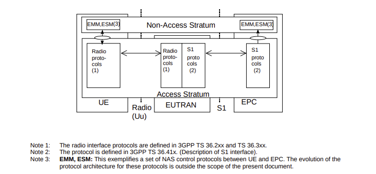
NAS messages may be piggybacked on AS messages, and you’ll also note the presence of the Evolved Packet System (EPS) Mobility Management (EMM) and Session Management (ESM) protocols on top of the Non-Access Stratum. We saw both appear in the next communication.
39	7.772736			LTE RRC UL_DCCH/NAS-EPS	110	RRCConnectionSetupComplete, Attach request, PDN connectivity request
41	8.378113			LTE RRC DL_DCCH/NAS-EPS	63	DLInformationTransfer, Authentication request
44	8.433136			LTE RRC UL_DCCH/NAS-EPS	38	ULInformationTransfer, Authentication response
45	8.521912			LTE RRC DL_DCCH/NAS-EPS	41	DLInformationTransfer, Security mode command
48	8.523621			LTE RRC UL_DCCH/NAS-EPS	46	ULInformationTransfer, Ciphered message
49	8.899994			LTE RRC DL_DCCH/NAS-EPS	36	DLInformationTransfer
The Attach request is an EMM message, while the PDN connectivity request is an ESM message, and both are encapsulated in the RRCConectionSetupComplete message sent by the UR. To understand the structure of NAS messages, we have to look at, you guessed it, another 3GPP TS. This time is it 3GPP TS 24.301 version 13.12.0 Release 13, entitled “Universal Mobile Telecommunications System (UMTS); LTE; 5G; Non-Access-Stratum (NAS) protocol for Evolved Packet System (EPS); Stage 3”. I promise I’m not making these names up. The PDN connectivity request is, according to the specification, sent by the UE to the network to initiate establishment of a Packet Data Network (PDN) connection (Section 8.3.20). It includes a variety of parameters, which which we were able see when expanding the data in Wireshark.
ESM message container
    Length: 41
    ESM message container contents: 0201d03127238080211001000010810600000000830600000000000d00000300000a00001000001600
        0000 .... = EPS bearer identity: No EPS bearer identity assigned (0)
        .... 0010 = Protocol discriminator: EPS session management messages (0x2)
        Procedure transaction identity: 1
        NAS EPS session management messages: PDN connectivity request (0xd0)
        0011 .... = PDN type: IPv4v6 (3)
        .... 0001 = Request type: Initial request (1)
        Protocol Configuration Options
            Element ID: 0x27
            Length: 35
            [Link direction: MS to network (0)]
            1... .... = Extension: True
            .... .000 = Configuration Protocol: PPP for use with IP PDP type or IP PDN type (0)
            Protocol or Container ID: Internet Protocol Control Protocol (0x8021)
            Protocol or Container ID: DNS Server IPv4 Address Request (0x000d)
                Length: 0x00 (0)
            Protocol or Container ID: DNS Server IPv6 Address Request (0x0003)
                Length: 0x00 (0)
            Protocol or Container ID: IP address allocation via NAS signalling (0x000a)
            Protocol or Container ID: IPv4 Link MTU Request (0x0010)
            Protocol or Container ID: APN rate control support indicator (0x0016)
The vast majority of them fall under Protocol Configuration Options (PCO). Thankfully there is some information about these options in Section 9.9.4.11 of TS 24.301. It reads:
See subclause 10.5.6.3 in 3GPP TS 24.008.
You’ve got to be kidding me. We’ll skip the big reveal and jump right to the description in TS 24.008.
The purpose of the protocol configuration options information element is to:
- transfer external network protocol options associated with a PDP context activation, and
- transfer additional (protocol) data (e.g. configuration parameters, error codes or messages/events) associated with an external protocol or an application.
A Packet Data Protocol (PDP) context is the connection over which the UE can send packets to the network. The options that immediately stuck out when investigating our DNS issue was the presence of the DNS Server IPv4 Address Request and DNS Server IPv6 Address Request. In the PDN connectivity request, these indicate that the UE is requesting these addresses from the network. We can see the response in the Attach accept message which includes an Activate default EPS bearer context ESM message.
125 73.928986 NAS-EPS 177 Attach accept, Activate default EPS bearer context request (PDN type IPv4 only allowed)
It includes its own set of protocol configuration options, providing responses for the requests made by the UE.
ESM message container
    Length: 86
    ESM message container contents: 5204c101091c08686f6c6f6772616d066d6e63303530066d636332333404677072730501644bab975e06fefe66660101583227228080211003030010810608080808830608080404000d0408080808000d0408080404
        0101 .... = EPS bearer identity: EPS bearer identity value 5 (5)
        .... 0010 = Protocol discriminator: EPS session management messages (0x2)
        Procedure transaction identity: 4
        NAS EPS session management messages: Activate default EPS bearer context request (0xc1)
        EPS quality of service
        Access Point Name
        PDN address
        APN aggregate maximum bit rate
        ESM cause
        Protocol Configuration Options
            Element ID: 0x27
            Length: 34
            [Link direction: Network to MS (1)]
            1... .... = Extension: True
            .... .000 = Configuration Protocol: PPP for use with IP PDP type or IP PDN type (0)
            Protocol or Container ID: Internet Protocol Control Protocol (0x8021)
            Protocol or Container ID: DNS Server IPv4 Address (0x000d)
                Length: 0x04 (4)
                IPv4: 8.8.8.8
            Protocol or Container ID: DNS Server IPv4 Address (0x000d)
                Length: 0x04 (4)
                IPv4: 8.8.4.4
8.8.8.8 and 8.8.4.4 are Google’s primary and secondary DNS server addresses and matched what we already observed in the output from the AT+CGCONTRDP AT command. The nRF9160 was able to successfully resolve DNS and connect to the Golioth cloud platform after completing this attach procedure. However, upon rebooting and capturing another modem trace, the device failed DNS and the sequence of messages revealed a few differences.
First of all, the SIB messages were post-fixed with -NB, indicating we were receiving system information from an NB-IoT E-UTRAN rather than LTE Cat-M1.
60	30.905853			LTE RRC DL_SCH_NB	73	SystemInformationBlockType1-NB
61	35.066010			LTE RRC DL_SCH_NB	73	SystemInformationBlockType1-NB
62	49.306519			LTE RRC DL_SCH_NB	73	SystemInformationBlockType1-NB
63	51.546601			LTE RRC DL_SCH_NB	73	SystemInformationBlockType1-NB
64	56.026764			LTE RRC DL_SCH_NB	73	SystemInformationBlockType1-NB
65	59.575012			LTE RRC DL_SCH_NB	87	SystemInformation-NB [ SIB2 SIB3 ]
Nevertheless, the general procedure looked fairly similar, and the familiar piggybacked attach request and PDN connectivity request was once again present.
70 59.777832 LTE RRC UL_DCCH_NB/NAS-EPS 104 RRCConnectionSetupComplete-NB, Attach request, PDN connectivity request
However, when investigating the contents of the PDN connectivity request, we observed a slightly different structure.
ESM message container
    Length: 42
    ESM message container contents: 0202d0317b00238080211001010010810600000000830600000000000d00000300000a00001000001600
        0000 .... = EPS bearer identity: No EPS bearer identity assigned (0)
        .... 0010 = Protocol discriminator: EPS session management messages (0x2)
        Procedure transaction identity: 2
        NAS EPS session management messages: PDN connectivity request (0xd0)
        0011 .... = PDN type: IPv4v6 (3)
        .... 0001 = Request type: Initial request (1)
        Extended protocol configuration options
            Element ID: 0x7b
            Length: 35
            [Link direction: MS to network (0)]
            1... .... = Extension: True
            .... .000 = Configuration Protocol: PPP for use with IP PDP type or IP PDN type (0)
            Protocol or Container ID: Internet Protocol Control Protocol (0x8021)
            Protocol or Container ID: DNS Server IPv4 Address Request (0x000d)
                Length: 0x00 (0)
            Protocol or Container ID: DNS Server IPv6 Address Request (0x0003)
                Length: 0x00 (0)
            Protocol or Container ID: IP address allocation via NAS signalling (0x000a)
            Protocol or Container ID: IPv4 Link MTU Request (0x0010)
            Protocol or Container ID: APN rate control support indicator (0x0016)
Rather than Procotol Configuration Options (PCO), there were Extended Protocol Configuration Options (ePCO). They are defined in Section 9.9.4.26 of TS 24.301.
The purpose of the extended protocol configuration options information element is to:
- transfer external network protocol options associated with a EPS bearer context activation, and
- transfer additional (protocol) data (e.g. configuration parameters, error codes or messages/events) associated with an external protocol or an application.
Sounds pretty similar to PCO. Looking at one more specification, 3GPP TS 29.274 version 13.13.0 Release 13, entitled “Universal Mobile Telecommunications System (UMTS); LTE; 3GPP Evolved Packet System (EPS); Evolved General Packet Radio Service (GPRS) Tunnelling Protocol for Control plane (GTPv2-C); Stage 3” , states the following in Section 7.2.1 Note 15.
An MME, SGW and PGW which supports NB-IoT and/or Non-IP PDN type shall support ePCO. A UE supporting NB-IoT access and/or Non-IP PDN type also support ePCO.
GTP is the GPRS Tunnelling Protocol, and GTP-C is the “control” section. LTE uses GTPv2, which is described as follows on the Wikipedia page.
The eGTP-C (or, GTPv2-C) protocol is responsible for creating, maintaining and deleting tunnels on multiple Sx interfaces. It is used for the control plane path management, tunnel management and mobility management. It also controls forwarding relocation messages; SRNS context and creating forward tunnels during inter LTE handovers.
Looking back at the diagram from TS 36.401, GTPv2 is the protocol that allows communication between the E-UTRAN and the EPC. That traffic is not observable from the modem trace, but TS 29.274 tells us that both the UE and the entities that make up the EPC must support ePCO when using NB-IoT. We already observed the UE support in the PDN connectivity request, and the accept and activate response was received shortly after.
83 70.641510 NAS-EPS 108 Attach accept, Activate default EPS bearer context request (PDN type IPv4 only allowed)
However, upon inspecting the contents, there were no ePCO responses to be found.
ESM message container
    Length: 49
    ESM message container contents: 5202c101091c08686f6c6f6772616d066d6e63303530066d636332333404677072730501644bab975e04fefec56c583291
        0101 .... = EPS bearer identity: EPS bearer identity value 5 (5)
        .... 0010 = Protocol discriminator: EPS session management messages (0x2)
        Procedure transaction identity: 2
        NAS EPS session management messages: Activate default EPS bearer context request (0xc1)
        EPS quality of service
        Access Point Name
        PDN address
        APN aggregate maximum bit rate
        ESM cause
        Control plane only indication
This was despite the fact the that the same message indicates support for ePCO.
EPS network feature support
    Element ID: 0x64
    Length: 2
    1... .... = Control plane CIoT EPS optimization: Supported
    .0.. .... = EMM-REGISTERED w/o PDN connectivity: Not supported
    ..0. .... = Support of EXTENDED SERVICE REQUEST for packet services: Not supported
    ...0 0... = CS-LCS: no information about support of location services via CS domain is available (0)
    .... .0.. = Location services via EPC: Not supported
    .... ..0. = Emergency bearer services in S1 mode: Not supported
    .... ...1 = IMS voice over PS session in S1 mode: Supported
    0... .... = Signalling for a maximum number of 15 EPS bearer contexts: Not supported
    .0.. .... = Interworking without N26 interface: Not supported
    ..0. .... = Restriction on the use of dual connectivity with NR: Not restricted
    ...0 .... = Restriction on enhanced coverage: Not restricted
    .... 1... = Extended protocol configuration options: Supported
    .... .0.. = Header compression for control plane CIoT EPS optimization: Not supported
    .... ..0. = S1-u data transfer: Not supported
    .... ...0 = User plane CIoT EPS optimization: Not supported
What Went Wrong
At this point everything was starting to make sense.
- When using the nRF9160 modem for LTE connectivity, offloaded sockets must be enabled, which forces the use of offloaded DNS resolution.
- The nRF9160 modem firmware was using PCO for LTE Cat-M1 networks and ePCO for NB-IoT.
- When a DNS server address was provided, either via PCO or ePCO, by the network, the offloaded DNS functionality in the modem firmware would always use it as the first option.
- If a DNS server address was not provided by the network, the offloaded DNS resolution would fail to resolve unless a fallback was explicitly set with
nrf_setdnsaddr. - Some NB-IoT networks are not compliant with 3GPP specifications, leading to DNS failures when using nRF91 series modem firmware.
So who is to blame for this state of affairs? The network provider seems to not be implementing the specification correctly, which certainly is not great. However, Nordic also does not fail gracefully in this scenario or document the possibility of its occurrence. In our investigation, we discovered a plethora tickets on their DevZone forum detailing issues with DNS on nRF91 series modems. Most of the threads either fizzled out without resolution, or there was a suggestion to set CONFIG_LEGACY_PDN_PCO=y, completely disabling the use of ePCO, which may cause issues in the event that ePCO is supported. In our testing, ensuring that a secondary DNS address is always configured via nrf_setdnsaddr appears to be a more reliable option.
However, I would argue that the details of this specific issue are not the root of the problem. The root of the problem is an ecosystem that is built on secretive, proprietary technology and complex specifications that even the people involved in writing them have trouble implementing. While some of us may have a strange obsession with combing through 3GPP documents, that shouldn’t be a prerequisite for a company to build a reliable cellular-enabled product. The root of the problem is that, even though we have performed a thorough investigation, tested extensively, and communicated with vendors about the issue, we are still guessing because the modem firmware is closed source and the mobile network operator (MNO) infrastructure is opaque.
A Call for Change
You may say this is the way it has always been, or that if you want something to change you better be ready to hire a small army of lawyers. We prefer a more optimistic, though perhaps naive, outlook.
The reality is that the most effective way to inspire change in a commercial context is to appeal to a major player’s self-interest. As previously noted, modem designers like Nordic may have limited control over which parts of the modem firmware can be open source and which cannot. However, given their embrace of open source application firmware, it is clear that they recognize the benefits of both building an ecosystem and allowing customers and other organizations to contribute.
For Nordic and other vendors like them, open source is not only the best thing for their customers, it is the best thing for their business. The same is true for MNOs and MVNOs. The number one reason we see customers opt to not use cellular when another connectivity option is on the table is due to concerns around cost and reliability. Because telecom is a heavily regulated industry, utilizing cellular connectivity when building a product almost always requires taking a dependency on a third party. In order to serve your customers well, you need to have a relationship with your vendors that is based on trust. Transparency is a foundational building block of trust, and vendors that are willing to embrace that will be able to differentiate in the market.
Until then, you can find us combing through 3GPP specifications and reverse engineering their infrastructure to ensure that our customers are able to build cellular-enabled devices with confidence.
An excellent writeup on an issue I’ve seen and reported before. It’s good to see how far Golioth is digging into these very complex issues. So is the medium-term solution to continue setting the secondary DNS manually?
@john.stuewe yes, we would recommend setting the secondary DNS server address manually for the time being. We’ll keep this thread updated as a more robust solution is developed.
Great article - have the same issue with modem_cellular and simcom7080G
It’s been six months. Has there been any progress on a long term solution or should we continue to hard code the secondary DNS?
@john.stuewe thanks for following up! As of
sdk-nrfv3.1.0, there is now aCONFIG_LTE_LC_DNS_FALLBACK_MODULEthat is enabled by default that will cause a DNS server configured in Zephyr to be used for fallback, or can be overridden withCONFIG_LTE_LC_DNS_FALLBACK_ADDRESS.