We’re preparing to do some testing around power consumption of different services on the Aludel Elixir, our open source hardware with the Nordic nRF9160 and the Espressif ESP32-C3. More specifically, we’re hoping to benchmark the time and energy it takes to acquire position and balance the energy usage versus the provided accuracy. As with anything in engineering, there are tradeoffs.
As I went to set up a new board to start pulling Wi-Fi access points like we did on the $2 Geofence article, I realized I didn’t document the process of loading that firmware onto the module. Long ago we wrote about loading ESP-AT onto an Espressif devboard, but with a module on a custom board, the process changes slightly.
What is ESP-AT
ESP-AT is a firmware binary offered by our friends at Espressif. It enables a standard set of AT commands to control the capabilities of the underlying ESP32 modems. Many of these are the same across different models of their modems, which is a helpful standardization when upgrading or moving across product lines. The underlying firmware that builds the binary is also available, so you can add custom commands and create your own images if needed.
We have used the ESP-AT image regularly in our hardware-in-the-loop (HIL) testing for the Golioth Firmware SDK, notably to give the nRF52840 access to the internet via Wi-Fi. This was a key consideration when adding the ESP32-C3 module to the Aludel Elixir board (as opposed to another Wi-Fi offering). Since the last post, we have also shown that the Wi-Fi modem can be a fallback when the Cellular capabilities of the nRF9160 are turned off. This was a driving force to adding a secondary Wi-Fi modem to our custom hardware for conference demos. We also benefited from being able to scan Access Points (APs) for our new location service.
How the modem is hooked up
We separated out the pins from initial programming (UART0) from the pins we would use to talk to the modem in AT mode (UART1). The latter in the default image are GPIO6/GPIO7 on the ESP32-C3-MINI module. This Hardware Connection page for the ESP-AT guide was helpful when designing the board.
We decided for Revision B of the Elixir not to use UART0 so that we didn’t need to maintain our own build of ESP-AT, so that it aligned with UART0 and UART1 being separated. For future revisions of the board, we want to ensure we have the ability to jumper over the serial connections or switch back to using UART0 for both functions like we did on RevA and then build a custom version of ESP-AT.
Programming and Testing
When it comes to actually programming the image, it’s pretty simple.
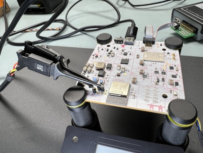
In the photo below, we use press fit connectors and some clamps to get a temporary connection to the broken out pins. We decided not to populate the pin headers because they don’t provide much user value aside from additional GPIO (the nRF9160 is constrained). In a pinch, I have also used dupont cables held up to these pins to program, but it is not production worthy (nor should I have ever admitted as much in writing). In production, a simple jig with pogo pins would serve this purpose well.
These wires are being sourced from a USB-to-serial dongle, I often use ones based on Silicon Labs parts. You’ll need to know which serial port shows up when the dongle is plugged in, like /dev/ttyUSB0. Windows and Mac will have different formats, but you’ll need to know which port to target in later steps.
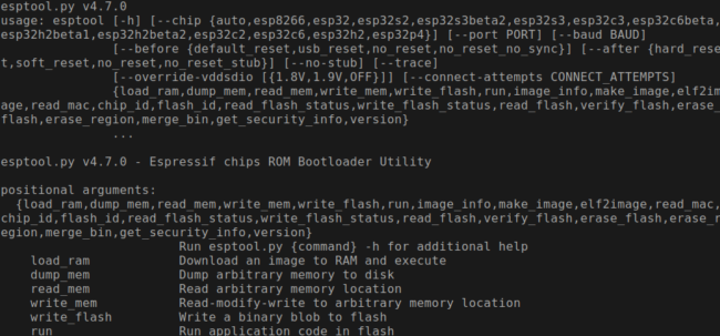
Once your hardware is connected, you’ll need Python 3.7+ and pip installed on your machine. Then to install esptool.py, you type:
pip install esptool
For more detailed instructions and troubleshooting, check out the Espressif docs page
Running esptool.py from the command line should look something like this:
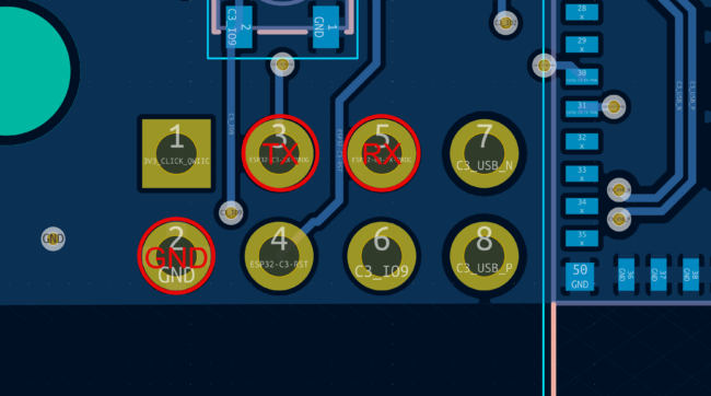
Now cross-connect your wires (TX from dongle wires to RX on the Elixir, and the reverse). Here’s another view of the 8 pin header where the pins will connect:
Next is to download the latest image from Espressif, if using the stock image (we are). Go to the Released Firmware page for your version of the ESP-AT image to download the zip. Always note in the URL or on the left side of the page that you’re targeting the correct device (in our case ESP32-C3) as there are significant differences between the versions. While esptool.py will check your image against your device, it’s always important to not risk loading errant firmware. At the time of this post, the latest firmware is v3.3.0.0, so we would replace {{version}} above with that number.
I’m going to open a terminal at the location of the file:
unzip ESP32-C3-MINI-1-AT-{{VERSION}}.zip
cd ESP32-C3-MINI-1-AT-{{VERSION}}/ESP32-C3-MINI-1-AT-{{VERSION}}
This will put us into the directory where we can access the esp-at.bin package.
To put the device in bootloader mode, hold down the MODE and RESET buttons, and then release RESET while still holding down MODE. When the device wakes up from reset and sees IO9 being held, it switches into the flash-based bootloader mode and will accept new images over UART0.
Finally, on your computer run the following lengthy command, replacing {{SERIAL_PORT}}with the address of your USB-to-serial dongle (mine is at /dev/ttyUSB0 when nothing else is plugged in).
esptool.py --chip auto --port /dev/{{SERIAL_PORT}} --baud 115200 --before default_reset --after hard_reset write_flash -z --flash_mode dio --flash_freq 40m --flash_size 4MB 0x0 bootloader/bootloader.bin 0x60000 esp-at.bin 0x8000 partition_table/partition-table.bin 0xd000 ota_data_initial.bin 0x1e000 at_customize.bin 0x1f000 customized_partitions/mfg_nvs.bin
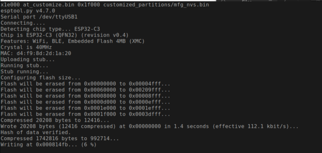
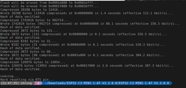
Successful programming will look like this:
Now we are ready to start sending commands from the nRF9160 over the ESP32-C3’s UART1 port, including querying Wi-Fi access points and using it as a secondary modem in the case of lack of cellular coverage.
We will be following up with more power measurement using this offloaded modem to scan for Wi-Fi, and the true costs of powering up a secondary modem for simple tasks. If you’re interested in our private alpha for locations services, please reach out via the announcement blog post. For any questions or troubleshooting with ESP-AT, we can always be found via our forum.

No comments yet! Start the discussion at forum.golioth.io