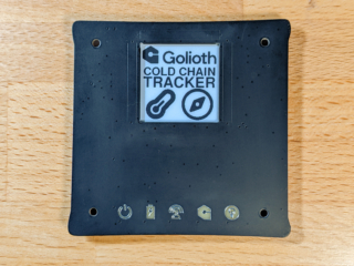
How do you show a device connected to and controlled from the Internet? Golioth is literally doing this every day, so we built a piece of custom hardware that shows what’s going on when a device is passing sensor data up to the cloud and receiving commands in return. We call it Ostentus, and it’s a beautiful combination of ePaper, back-lit LEDs, and capacitive touch.
The origins of the word Ostentus come from the Latin: expose to view, exhibit, show. This is a perfect codename for the modular faceplate we built to show off Golioth’s reference designs. Let’s see it in action and dive into the details of how we built it.
Add to any project via I2C
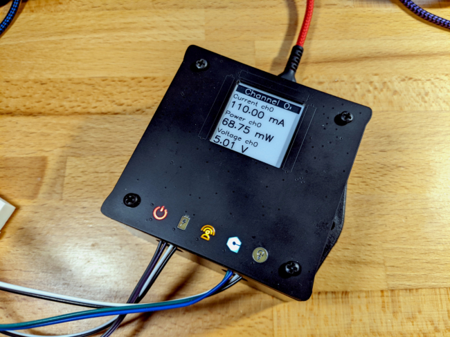
Ostentus communicates with its host hardware over i2c, receiving a simple set of commands to update the display and LEDs.
Golioth is headed to the Embedded World conference next week and you’ll see these faceplates on a number of different demo units. They scroll through different sensor readings, including the option for a summary page. At boot, they display the logo that accompanies the demo. They can also be used to read out connection and other information from the device.
There’s a helper library that is added to an existing project as a submodule. For most of our demos, we just insert a couple dozen lines of code to pipe six(ish) different readings to the display.
Ostentus’ Hardware Origin Story
User interfaces grow in complexity very quickly. Our primary goal was to make it simple to add Ostentus to any IoT project, for any of the SDKs that we support (3 and growing!). That means simplicity from both the hardware and firmware side of things.
The latest Golioth reference designs use the MikroElectronika Click ecosystem for sensors, and include at least to Qwiic connectors. This means two things:
- We don’t have a ton of extra pins to drive something like a display direct from our chosen microcontroller
- I2C is already used in pretty much everything we demonstrate
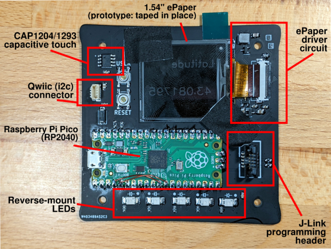
We chose to utilize I2C and have the Ostentus board act as just another I2C peripheral.
Next, we’ve done a lot of work with ePaper through our trainings (and other shenanigans). It is kind of magical how easy it is to read, and how it retains an image even when powered off. We ordered an assortment of different displays in December to spec them out for our purposes.
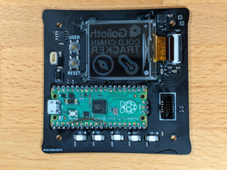
The chip shortage drove our choice of microcontrollers. We landed on the RP2040 microcontroller because of its knack to remain in-stock. It also helps that it’s a powerhouse, with 133 MHz dual-core, “PIO” which are hardware-based state machines (more on those later), abundant pins, SRAM, external flash…all for a somewhat low price. We had originally planned to populate the RP2040 and its necessary circuitry directly on the PCB, but the ease, availability, and cost of the Pico boards led us to include them as modules.
Finally, we have a wealth of past experience producing circuit boards that themselves were meant to look amazing without being placed in a case. This informed the board design and passive component decisions for a fantastic aesthetic. The LEDs are on the underside of the board, shining up through the substrate to appear as illuminated icons. There are also three capacitive touch pads that allow for user feedback. All of this is wrapped in matte black solder mask, making it look more like a (Dark) Apple product and less a PCB. The result is a perfect replacement for the plain plastic covers of the project boxes we told you about last week.
Is it Firmware or Software?
The heavy lifting for the display graphics is all handled by the RP2040 on the board. When we landed on this chip we looked around for other projects using it along with ePaper and found the Pimoroni Badger 2040. That dev board is based around MicroPython, which we hadn’t originally set out to use, but it makes a lot of sense. You can plug USB into it and upload new graphics without rebuilding/reflashing firmware. That has modularity written all over it! We did some early testing to see if the pimoroni-pico repository could be extended for Golioth’s needs and it looked promising.
Unfortunately, Ostentus didn’t have enough physical space for the same ePaper display. We spun up our own driver based on the Good Display sample code for the GDEH0154D67, a 1.54″ square display that packs in a remarkable 200×200 pixel resolution.
Communications proved a bit of a challenge. Ostentus is an I2C peripheral device and needs to listen on the bus while a lot of other stuff is going on. We were lucky to find Daniel Gorbea’s I2C multi-address library. It builds for the Pico-SDK, utilizing the PIO and interrupts for tight hardware timing. This receives incoming I2C messages over the Qwiic connector, immediately updating LED state for certain commands, and buffering the rest for MicroPython to access.
MicroPython makes images, fonts, and screen control a breeze. There was a learning curve in getting the C code to play nicely with the Python, but it’s not to hard to pick up. For this year’s conference we’ve set up the MicroPython layer to run a slideshow of sensor values. The controlling device registers each slide over I2C, sending a string as the label and assigning a unique key. That key is later used to send updated values as they become available.
What a Show!
It’s been a whirlwind adventure getting to this point. But let’s be honest, most of the Internet of Things industry happens in abstract and non-obvious ways. Golioth moves the ball on securely connecting and controlling microcontroller-level devices, and lots of them. Ostentus makes it much easier for us to show that story in real-time, at a booth, in the middle of tens of thousands of awesome embedded engineers. We can’t wait you see you next week. At the very least, you’ll want to stop by for a hands-on view of our sleek new Ostentus board!

No comments yet! Start the discussion at forum.golioth.io